Dell W-AP200 Series Installation Guide
Summary
Dell Networking W-AP200 Series Wireless Access Point Installation Guide for W-AP204 and W-AP205 models. The guide covers IEEE 802.11n/ac support, MIMO technology, PoE deployment, LED behavior, physical installation, controller provisioning, and network connectivity setup for enterprise wireless LAN deployments. Target users are network administrators and wireless engineers installing Dell W-Series access points with Mobility Controllers.
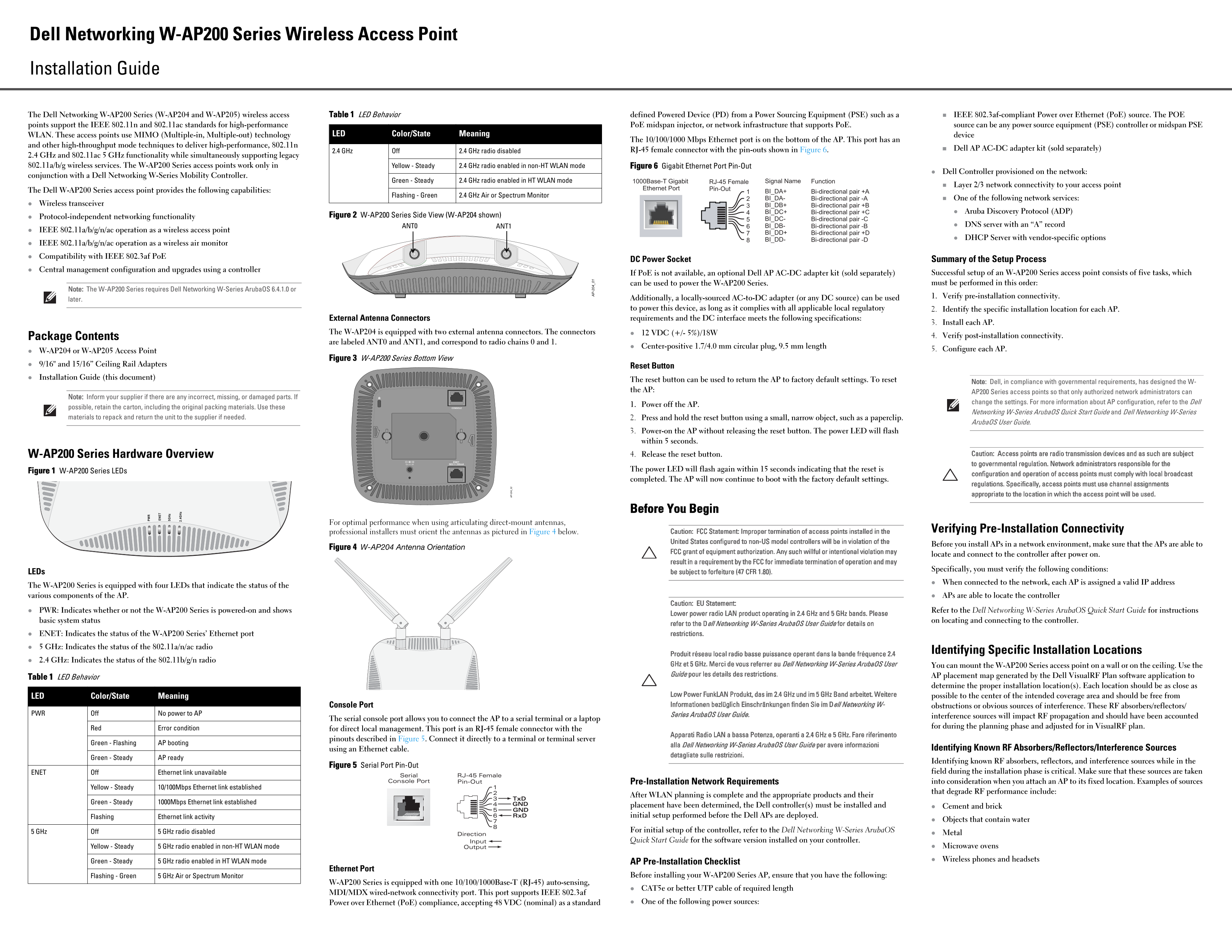
Page 1 Text Content
Dell Networking W-AP200 Series Wireless Access Point Installation Guide
The Dell Networking W-AP200 Series (W-AP204 and W-AP205) wireless access Table 1 LED Behavior defined Powered Device (PD) from a Power Sourcing Equipment (PSE) such as a IEEE 802.3af-compliant Power over Ethernet (Po E) source. The POE points support the IEEE 802.11n and 802.11ac standards for high-performance Po E midspan injector, or network infrastructure that supports Po E. source can be any power source equipment (PSE) controller or midspan PSE
WLAN. These access points use MIMO (Multiple-in, Multiple-out) technology LED Color/State Meaning device
The 10/100/1000 Mbps Ethernet port is on the bottom of the AP. This port has an
and other high-throughput mode techniques to deliver high-performance, 802.11n
WP Dell AP AC-DC adapter kit (sold separately)
2.4 GHz Off 2.4 GHz radio disabled RJ-45 female connector with the pin-outs shown in Figure 6.
2.4 GHz and 802.11ac 5 GHz functionality while simultaneously supporting legacy
802.11a/b/g wireless services. The W-AP200 Series access points work only in Yellow - Steady 2.4 GHz radio enabled in non-HT WLAN mode Figure 6 Gigabit Ethernet Port Pin-Out
Dell Controller provisioned on the network:
conjunction with a Dell Networking W-Series Mobility Controller.
Green - Steady G4. 2.4 GHz radio enabled in HT WLAN mode
1000Base-T Gigabit RJ-45 Female Signal Name Function
Layer 2/3 network connectivity to your access point
Ethernet Port Pin-Out
The Dell W-AP200 Series access point provides the following capabilities: BI_DA+ Bi-directional pair +A
Flashing - Green 2.4 GHz Air or Spectrum Monitor
BI_DA- Bi-directional pair -A One of the following network services:
Wireless transceiver BI_DB+
Bi-directional pair +B
BI_DC+ Bi-directional pair +C Aruba Discovery Protocol (ADP)
Protocol-independent networking functionality Figure 2 W-AP200 Series Side View (W-AP204 shown)
BI_DC- Bi-directional pair -C
ANT1ANT0 BI_DB- Bi-directional pair -B DNS server with an “A” record
IEEE 802.11a/b/g/n/ac operation as a wireless access point
BI_DD+ Bi-directional pair +D
DHCP Server with vendor-specific options
BI_DD- Bi-directional pair -D
IEEE 802.11a/b/g/n/ac operation as a wireless air monitor Compatibility with IEEE 802.3af Po E
DC Power Socket Summary of the Setup Process
Central management configuration and upgrades using a controller
If Po E is not available, an optional Dell AP AC-DC adapter kit (sold separately) Successful setup of an W-AP200 Series access point consists of five tasks, which can be used to power the W-AP200 Series. must be performed in this order:
Note: The W-AP200 Series requires Dell Networking W-Series Aruba OS 6.4.1.0 or
1. Verify pre-installation connectivity.
later. Additionally, a locally-sourced AC-to-DC adapter (or any DC source) can be used to power this device, as long as it complies with all applicable local regulatory 2. Identify the specific installation location for each AP. External Antenna Connectors requirements and the DC interface meets the following specifications:
3. Install each AP.
The W-AP204 is equipped with two external antenna connectors. The connectors 12 VDC (+/- 5%)/18W
Package Contents 4. Verify post-installation connectivity.
are labeled ANT0 and ANT1, and correspond to radio chains 0 and 1.
Center-positive 1.7/4.0 mm circular plug, 9.5 mm length
5. Configure each AP.
W-AP204 or W-AP205 Access Point
Figure 3 W-AP200 Series Bottom View
9/16" and 15/16” Ceiling Rail Adapters
Reset Button
Installation Guide (this document)
The reset button can be used to return the AP to factory default settings. To reset
Note: Dell, in compliance with governmental requirements, has designed the W-
the AP:
AP200 Series access points so that only authorized network administrators can
Note: Inform your supplier if there are any incorrect, missing, or damaged parts. If
change the settings. For more information about AP configuration, refer to the Dell
1. Power off the AP.
possible, retain the carton, including the original packing materials. Use these
Networking W-Series Aruba OS Quick Start Guide and Dell Networking W-Series
materials to repack and return the unit to the supplier if needed. 2. Press and hold the reset button using a small, narrow object, such as a paperclip.
Aruba OS User Guide.
3. Power-on the AP without releasing the reset button. The power LED will flash within 5 seconds.
W-AP200 Series Hardware Overview 4. Release the reset button. Caution: Access points are radio transmission devices and as such are subject to governmental regulation. Network administrators responsible for the
Figure 1 W-AP200 Series LEDs The power LED will flash again within 15 seconds indicating that the reset is
configuration and operation of access points must comply with local broadcast
completed. The AP will now continue to boot with the factory default settings.
regulations. Specifically, access points must use channel assignments appropriate to the location in which the access point will be used.
AP -2 _0 Before You Begin
For optimal performance when using articulating direct-mount antennas,
professional installers must orient the antennas as pictured in Figure 4 below. Caution: FCC Statement: Improper termination of access points installed in the Verifying Pre-Installation Connectivity
United States configured to non-US model controllers will be in violation of the
Before you install APs in a network environment, make sure that the APs are able to
Figure 4 W-AP204 Antenna Orientation
FCC grant of equipment authorization. Any such willful or intentional violation may
locate and connect to the controller after power on.
result in a requirement by the FCC for immediate termination of operation and may
Specifically, you must verify the following conditions:
LEDs be subject to forfeiture (47 CFR 1.80).
When connected to the network, each AP is assigned a valid IP address
The W-AP200 Series is equipped with four LEDs that indicate the status of the
various components of the AP. APs are able to locate the controller
Caution: EU Statement:
PWR: Indicates whether or not the W-AP200 Series is powered-on and shows Refer to the Dell Networking W-Series Aruba OS Quick Start Guide for instructions
Lower power radio LAN product operating in 2.4 GHz and 5 GHz bands. Please
basic system status on locating and connecting to the controller.
refer to the Dell Networking W-Series Aruba OS User Guide for details on
ENET: Indicates the status of the W-AP200 Series’ Ethernet port restrictions. 5 GHz: Indicates the status of the 802.11a/n/ac radio
Identifying Specific Installation Locations
Produit réseau local radio basse puissance operant dans la bande fréquence 2.4
2.4 GHz: Indicates the status of the 802.11b/g/n radio
GHz et 5 GHz. Merci de vous referrer au Dell Networking W-Series Aruba OS User You can mount the W-AP200 Series access point on a wall or on the ceiling. Use the Guide pour les details des restrictions. AP placement map generated by the Dell Visual RF Plan software application to
Table 1 LED Behavior
determine the proper installation location(s). Each location should be as close as
Low Power Funk LAN Produkt, das im 2.4 GHz und im 5 GHz Band arbeitet. Weitere possible to the center of the intended coverage area and should be free from
LED Color/State Meaning
Console Port Informationen bezlüglich Einschränkungen finden Sie im Dell Networking W- obstructions or obvious sources of interference. These RF absorbers/reflectors/
PWR Off No power to AP Series Aruba OS User Guide.
interference sources will impact RF propagation and should have been accounted
The serial console port allows you to connect the AP to a serial terminal or a laptop
for during the planning phase and adjusted for in Visual RF plan.
Red Error condition for direct local management. This port is an RJ-45 female connector with the
Apparati Radio LAN a bassa Potenza, operanti a 2.4 GHz e 5 GHz. Fare riferimento
pinouts described in Figure 5. Connect it directly to a terminal or terminal server
Green - Flashing AP booting
alla Dell Networking W-Series Aruba OS User Guide per avere informazioni
using an Ethernet cable. Identifying Known RF Absorbers/Reflectors/Interference Sources
detagliate sulle restrizioni.
Green - Steady AP ready
Identifying known RF absorbers, reflectors, and interference sources while in the
Figure 5 Serial Port Pin-Out
ENET Off Ethernet link unavailable field during the installation phase is critical. Make sure that these sources are taken
Serial RJ-45 Female Console Port Pin-Out Pre-Installation Network Requirements into consideration when you attach an AP to its fixed location. Examples of sources
Yellow - Steady 10/100Mbps Ethernet link established
that degrade RF performance include:
After WLAN planning is complete and the appropriate products and their
Green - Steady 1000Mbps Ethernet link established
GND placement have been determined, the Dell controller(s) must be installed and
Cement and brick
GND Flashing Ethernet link activity Rx D initial setup performed before the Dell APs are deployed.
Objects that contain water
5 GHz Off 5 GHz radio disabled For initial setup of the controller, refer to the Dell Networking W-Series Aruba OS
Direction Metal
Input Quick Start Guide for the software version installed on your controller.
Yellow - Steady 5 GHz radio enabled in non-HT WLAN mode Output Microwave ovens Wireless phones and headsets
Green - Steady 5 GHz radio enabled in HT WLAN mode AP Pre-Installation Checklist
Ethernet Port
Flashing - Green 5 GHz Air or Spectrum Monitor Before installing your W-AP200 Series AP, ensure that you have the following:
W-AP200 Series is equipped with one 10/100/1000Base-T (RJ-45) auto-sensing,
CAT5e or better UTP cable of required length
MDI/MDX wired-network connectivity port. This port supports IEEE 802.3af
Power over Ethernet (Po E) compliance, accepting 48 VDC (nominal) as a standard One of the following power sources:
Page Summary Contents For Dell W-AP200 Series Installation Guide
Manual Details
| Brand | Dell |
|---|---|
| Pages | 2 |
| File Size | 755.35 KB |
| Published | June 25, 2026 |
Enter the captcha to get the download link:

Frequently Asked Questions
How can I reset the W-AP200 Series to factory default settings?
Power off, press and hold the reset button with a small object, power on without releasing it, then release the button.
What standards does the W-AP200 Series support for wireless connectivity?
It supports IEEE 802.11a/b/g/n/ac operation using MIMO technology and can operate in 2.4 GHz or 5 GHz bands.
Is an external power adapter necessary if PoE is unavailable?
Yes, the optional Dell AP AC-DC adapter kit must be used. A locally sourced AC-to-DC adapter or DC source that complies with specifications can also work.
What indicators show the Access Point was successfully reset?
The power LED will flash within 5 seconds (initial press) and again within 15 seconds (completion). The AP then boots with factory default settings.