# A B C D E F G H I J K L M N O P Q R S T U V W X Y Z

Dell PowerConnect W-IAP175P AC Installation Guide

Summary

This is the installation guide for the Dell PowerConnect W-IAP175 Outdoor Instant Access Point. The manual provides detailed instructions for deploying the environmentally hardened, outdoor-rated wireless access point. It covers three power options (PoE+, AC powered, and PSE device), hardware overview, outdoor planning and deployment considerations, antenna installation, weatherproofing connections, and mounting procedures. The guide also includes safety and regulatory compliance information. It is intended for wireless network engineers and IT professionals responsible for deploying outdoor wireless infrastructure using Dell PowerConnect access points.
📄 Preview 📖 Table of Contents Contents PAGE OF 32

Page 1 Text Content

Dell Power Connect W-IAP175 Outdoor Instant Access Point Installation Guide

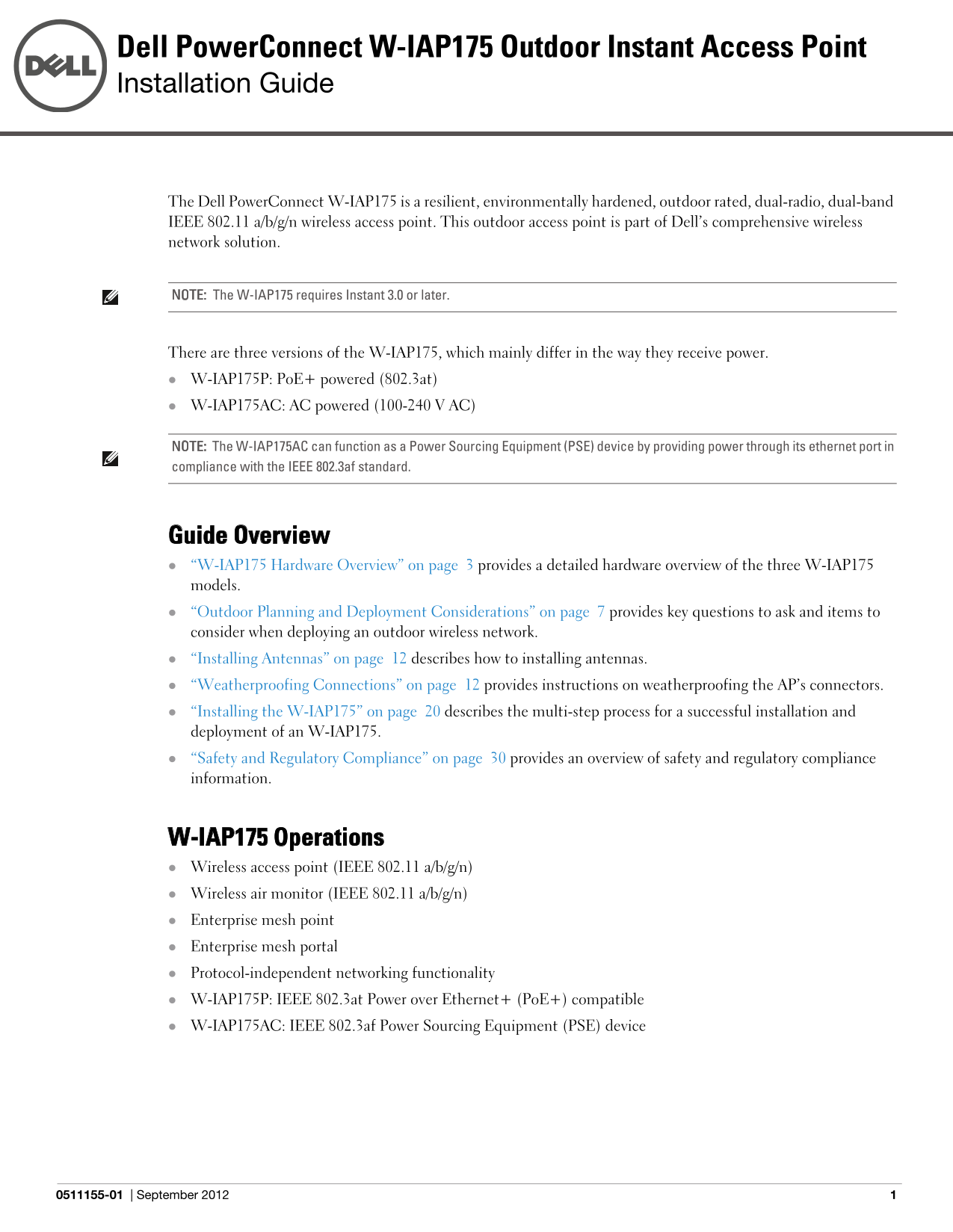
The Dell Power Connect W-IAP175 is a resilient, environmentally hardened, outdoor rated, dual-radio, dual-band IEEE 802.11 a/b/g/n wireless access point. This outdoor access point is part of Dell’s comprehensive wireless network solution.

NOTE: The W-IAP175 requires Instant 3.0 or later.

There are three versions of the W-IAP175, which mainly differ in the way they receive power. W-IAP175P: Po E+ powered (802.3at) W-IAP175AC: AC powered (100-240 V AC)

NOTE: The W-IAP175AC can function as a Power Sourcing Equipment (PSE) device by providing power through its ethernet port in compliance with the IEEE 802.3af standard.

Guide Overview “W-IAP175 Hardware Overview” on page 3 provides a detailed hardware overview of the three W-IAP175 models. “Outdoor Planning and Deployment Considerations” on page 7 provides key questions to ask and items to consider when deploying an outdoor wireless network. “Installing Antennas” on page 12 describes how to installing antennas. “Weatherproofing Connections” on page 12 provides instructions on weatherproofing the AP’s connectors. “Installing the W-IAP175” on page 20 describes the multi-step process for a successful installation and deployment of an W-IAP175. “Safety and Regulatory Compliance” on page 30 provides an overview of safety and regulatory compliance information.

W-IAP175 Operations Wireless access point (IEEE 802.11 a/b/g/n) Wireless air monitor (IEEE 802.11 a/b/g/n) Enterprise mesh point Enterprise mesh portal Protocol-independent networking functionality W-IAP175P: IEEE 802.3at Power over Ethernet+ (Po E+) compatible W-IAP175AC: IEEE 802.3af Power Sourcing Equipment (PSE) device

0511155-01 September 2012

Page Summary Contents For Dell PowerConnect W-IAP175P AC Installation Guide

Page 1 Dell Power Connect W-IAP175 Outdoor Instant Access Point Installation Guide The Dell Power Connect W-IAP175 is a resilient, environmentally hardened, outdoor rated, dual-radio, dual-band IEEE 802.11 a...
Page 2 Package Contents W-IAP175 Access Point W-IAP175 Mounting Bracket Solar Shield Pole Anchors x 2 M4 x 16 bolts, flat washers, and spring washers x4 (These bolts are attached to the solar shield) M6 x 30...
Page 3 W-IAP175 Hardware Overview The following section describes the hardware features of the W-IAP175. Figure 1 W-IAP175 Overview (W-IAP175P shown) Antenna Interface (Radio 1) Antenna Interface (Radio 0) U...
Page 4 USB Console Interface A USB serial console port is provided for connection to a terminal, allowing direct local management. Use the included USB console cable to connect to the AP. You can download th...
Page 5 injector. Inversely, the W-IAP175AC can act as a PSE device to provide IEEE802.3af Po E power to devices connected to the ethernet port. Grounding Point Always remember to protect your W-IAP175 by ins...
Page 6 Table 3 W-IAP175P LED Status Indicators (Continued) LED Function Indicator Status RSSI (Radio 0) RSSI Level for Radio 0 Off RSSI disabled/no signal 4 Step Progressive Bars Each bar represents a progre...
Page 7 Table 4 W-IAP175AC LED Status Indicators (Continued) LED Function Indicator Status POE Displays PSE power Off Non-powered device (0Ω<Rport<200Ω) or Port output status open (Rport>1MΩ) Green P...
Page 8 Scale Requirements The potentially immense scale of outdoor deployments requires consideration of factors that may not be as important in a typical indoor deployment: Range (distance): Range or distan...
Page 9 Figure 4 Line of Sight Radio Line of Sight Visual Line of Sight If there are obstacles in the radio path, there may still be a radio link but the quality and strength of the signal will be affected. C...
Page 10 Table 5 Antenna Minimum Height and Clearance Requirements Max Clearance for Total Clearance Approximate Clearance Total Link Distance 60% of First Fresnel Required at for Earth Curvature Zone at 5.8 G...
Page 11 Antenna Position and Orientation Once the required antenna height has been determined, other factors affecting the precise position of the wireless bridge or mesh link must be considered: Be sure ther...
Page 12 Determine if conduits, bracing, or other structures are required for safety or protection of the cable. For lightning protection at the power injector end of the cable, consider using a lightning arre...
Page 13 Connected Antennas” on page 15. For weatherproofing cable connections, see “Weatherproofing Cable Connections” on page 18. NOTE: The following instructions assume that you have installed a lightning a...
Page 14 Figure 7 Cable Connections Connectors on bottom of antenna N-type connector on an RF cable N-type connector on a pigtail Important Points to Remember Do not cover the weep holes on the antennas. Doing...
Page 15 Weatherproofing Directly Connected Antennas NOTE: The following instructions assume that you have installed a lightning arrestor between your W-IAP175. First Wrapping of Tape 1. Before wrapping the an...
Page 16 Wrapping of Butyl Rubber 1. Cut a 3/4” (19 mm) strip of butyl rubber. 2. Wrap the strip of rubber around the taped connector (Figure 9) 3. Join the two ends by pushing them together until there is no ...
Page 17 Second Wrapping of Tape 1. Cut a 4” (100 mm) strip of electrical tape from the roll. 2. Where you begin wrapping depends on the orientation of the antenna. Water should flow in the opposite direction ...
Page 18 Weatherproofing Cable Connections First Wrapping of Tape 1. Prepare the antenna connector by cleaning and drying it. 2. Cut a 4” (100 mm) strip of electrical tape from the roll. Pre-cutting the tape i...
Page 19 Wrapping of Butyl Rubber 1. Cut a piece of butyl rubber large enough to wrap around the connector and extended past the first layer of tape. 2. Wrap the strip of rubber around the taped connector (Fig...
Page 20 Second Wrapping of Tape 1. Cut a 4” (100 mm) strip of electrical tape from the roll. 2. Using 3/4” (19mm) electrical tape, begin wrapping at the connector and create four layers. 3. After completing t...
Page 21 Installing the W-IAP175 on a Pole 1. Attach the W-IAP175 on the mounting bracket using the two M6 x30 bolts (with flat and spring washers) on each side of the mounting bracket. Figure 16 Attaching the...
Page 22 Installing the W-IAP175 on a Wall 1. Begin by marking the screw points on the wall in the location you have selected. a. Put the mounting bracket on the installation position against the wall. b. Mark...
Page 23 Figure 19 Attaching the AP to the Mounting Bracket Grounding the W-IAP175 The grounding must be completed before powering up the W-IAP175. The resistance of grounding wire should be less than 5 ohm an...
Page 24 Connecting the Ethernet Cable (W-IAP175P) To ensure that your outdoor access point (AP) maintains ethernet connectivity and Power over Ethernet (Po E), you must use the included weatherproof connector...
Page 25 Connecting the Ethernet Cable (W-IAP175AC) To ensure that your outdoor access point (AP) maintains ethernet connectivity and Power over Ethernet (Po E), you must use the included weatherproof connecto...
Page 26 Figure 23 Connecting the Ethernet cable Connecting the Power Cable (W-IAP175 AC) CAUTION: Installation and service of Dell products should be performed by Professional Installers in a manner that is c...
Page 27 Connecting a Power Cable to the W-IAP175AC 1. Remove the protective cap on the power interface. 2. Insert the power cable connector into the power interface and hand-fasten the waterproof cover. 3. Wa...
Page 28 Product Specifications Mechanical Dimensions (H x W x D) 10.2 inches x 9.4 inches x 4.1 inches 26 cm x 24 cm x 10.5 cm Weight: 7 lbs/3.25 kg Shipping Dimensions (H x W x D) 12.9 inches x 12.6 inches x...
Page 29 Wireless LAN AP type: Dual-radio, dual-band 802.11n outdoor Supported frequency bands (country-specific restrictions apply): 2.400 to 2.4835 GHz 5.150 to 5.250 GHz 5.250 to 5.350 GHz 5.470 to 5.725 GH...
Page 30 Safety and Regulatory Compliance Dell provides a multi-language document containing country specific restrictions and additional safety and regulatory information for all Dell hardware products. The D...
Page 31 Proper Disposal of Dell Equipment For the most current information about Global Environmental Compliance and Dell products, see dell.com. Waste of Electrical and Electronic Equipment Dell products at ...
Page 32 Philippines Type-Approval No. ESD-CPE-1004995C UAE (W-IAP175P) TRA REGISTERED No: ER0055290/11 DEALER No: DA0039425/10 UAE (W-IAP175AC) TRA REGISTERED No: ER0082364/12 DEALER No: DA0039425/10 Contacti...

Manual Details

Brand Dell
Pages 32
File Size 2.66 MB
Published June 26, 2026
5 views

Enter the captcha to get the download link:

captcha

Frequently Asked Questions

Does the W-IAP175AC support Power over Ethernet?

Yes, the W-IAP175AC can function as a Power Sourcing Equipment (PSE) device providing power via the ethernet port in compliance with IEEE 802.3af.

What is required to power the W-IAP175P model?

The W-IAP175P is PoE+ (802.3at) powered and does not include an internal power interface.

How do I connect to the AP for local management?

Use the included USB console cable and connect to the USB console interface. The terminal settings are 9600 baud, 8 data bits, no parity, 1 stop bit, and no flow control.

What antennas are required for the W-IAP175?

The unit requires detachable outdoor-rated antennas. Select the correct type to support the required frequency band (2.4 or 5 GHz) and coverage pattern.