Dell S3222HG Monitor Simplified Service Manual
Summary
This service manual covers the Dell S3220DGS 31.5-inch LCD monitor. It includes important safety notices, service procedures, disassembly instructions, and technical specifications. The manual is intended for trained service technicians who need to repair or maintain this Dell monitor model.
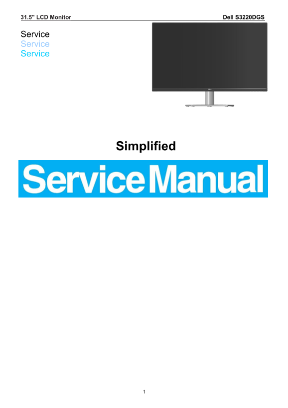
Page 1 Text Content
31.5" LCD Monitor Dell S3220DGS
Service Service Service
Simplified
Page Summary Contents For Dell S3222HG Monitor Simplified Service Manual
Page 1
31.5" LCD Monitor Dell S3220DGS Service Service Service Simplified
Page 2
Important Safety Notice Proper service and repair is important to the safe, reliable operation of all DELL Company Equipment. The service procedures recommended by DELL and described in this service m...
Page 3
1. Exploded view diagram with list of items
Page 4
No. Description Q’ty 1 MIDDLE_FRAME 1 2 Cover_IO 1 3 REAR_COVER NA 1 4 KEY 1 5 KEY_POWER 1 6 STAND_BUTTON 1 7 Latch 1 8 MAINFRAME 1 9 BEZEL_BTM 1 10 BKT_LOCKER 1 No. Part No. Description Q’ty 11 SPRIN...
Page 5
2. Wiring connectivity diagram
Page 6
3. Mechanical Instruction Tools Required List the type and size of the tools that would typically can be used to disassemble the product to a point where components and materials requiring selective ...
Page 7
3.1 Disassembly Procedures: Step Figure Remark Turn off power, S1.Before Unplug external cables disassemble from product S2.Remove the STAND-BASE ASS’Y Use a Philips-head screwdriver to remove 4 scr...
Page 8
separate the bezel and rear cove follow the arrows in sequence, then you can take out rear cover. Tear off the aluminum foils and Disconnect the cables S4. Remove the main frame Use a Philips-head scr...
Page 9
Remove the Mylar. Use a Philips-head screwdriver to remove 4 screws for unlocking the main board and the adapter board (No.1~8 screw size=D3x6, S5.Remove main board and power Torque: 6±1kgf.cm) board ...
Page 10
Use a Philips-head screwdriver to remove 20 screws for unlocking the middle plastic bezel with the whole unit, and then remove the middle plastic bezel carefully. (No.1~20 screw S6.Remove the size=M3x...
Page 11
3.2 Assembly Procedures: Step Figure Remark Use a Philips-head screwdriver to tighten 4 screws for locking the S1.Assembly the Key board Key board (No.1~4 screw size=Q2x2.5, Torque=0.9±0.4kgf.cm) Conn...
Page 12
Connect all of the cables Use a Philips-head screwdriver to screw 4 screws for locking the main board and the adapter board (No.1~8 screw size=D3x6, Torque: 6±1kgf.cm) (No.9 screw size=M4x6, Torque: 6...
Page 13
Connect the cables Paste the aluminum foils Use a Philips-head screwdriver to screw 4 screws for locking Rear S6.Assembly the cover. Rear cover (No.1~4 screw size=M4x10; Torque: 12±2kgf.cm)
Page 14
S7.Assembly the Stand
Page 15
4. Trouble shooting instructions
Manual Details
| Brand | Dell |
|---|---|
| Pages | 20 |
| File Size | 5.66 MB |
| Published | June 20, 2026 |
4 views
Enter the captcha to get the download link:

Frequently Asked Questions
What tools are required to disassemble the monitor?
Phillip head screwdriver, hex screwdriver, and a penknife.
What safety precautions must be taken when handling the LCD module?
Mount using corner holes, avoid pressing the panel, protect from ESD, and ground personnel with a wristband.
What are the specific torque requirements for the stand screws?
Use M4x10 screws with a torque of 12±2kgf.cm.
How should the LCD panel be cleaned?
Wipe with a soft material; avoid dirty or rough cloths.