# A B C D E F G H I J K L M N O P Q R S T U V W X Y Z

Dell Monitor Simplified Service Manual

Summary

This comprehensive service guide provides in-depth instructions for maintenance, troubleshooting, and sophisticated repair of your advanced electronic display unit. It details complex wiring diagrams, component identification via exploded views, and precise step-by-step disassembly/assembly procedures requiring specialized tools. The manual also serves as a vital resource for qualified technicians, covering safety protocols, connectivity solutions for USB peripherals and Ethernet, and diagnostics for common operational issues to ensure reliable performance.
📄 Preview 📖 Table of Contents Contents PAGE OF 21

Page 1 Text Content

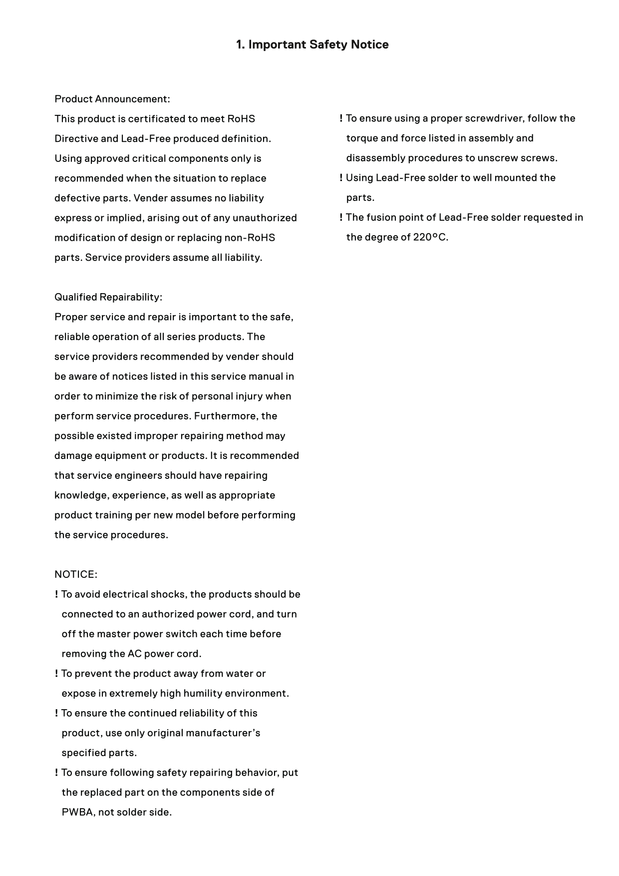
1. Important Safety Notice

Product Announcement:

This product is certificated to meet Ro HS ! To ensure using a proper screwdriver, follow the Directive and Lead-Free produced definition. torque and force listed in assembly and Using approved critical components only is disassembly procedures to unscrew screws. recommended when the situation to replace ! Using Lead-Free solder to well mounted the defective parts. Vender assumes no liability parts. express or implied, arising out of any unauthorized ! The fusion point of Lead-Free solder requested in modification of design or replacing non-Ro HS the degree of 220°C.

parts. Service providers assume all liability.

Qualified Repairability: Proper service and repair is important to the safe, reliable operation of all series products. The service providers recommended by vender should be aware of notices listed in this service manual in order to minimize the risk of personal injury when perform service procedures. Furthermore, the possible existed improper repairing method may damage equipment or products. It is recommended that service engineers should have repairing knowledge, experience, as well as appropriate product training per new model before performing the service procedures.

NOTICE: ! To avoid electrical shocks, the products should be connected to an authorized power cord, and turn off the master power switch each time before removing the AC power cord. ! To prevent the product away from water or expose in extremely high humility environment. ! To ensure the continued reliability of this product, use only original manufacturer’s specified parts. ! To ensure following safety repairing behavior, put the replaced part on the components side of PWBA, not solder side.

Page Summary Contents For Dell Monitor Simplified Service Manual

Page 1 1. Important Safety Notice Product Announcement: This product is certificated to meet Ro HS ! To ensure using a proper screwdriver, follow the Directive and Lead-Free produced definition. torque and f...
Page 2 2. Exploded view diagram with list of items
Page 3 3. Wiring Connectivity Diagram Panel 20W speaker 20W speaker Driver board HDMI4 USB type C with PD 90W
Page 4 4. Disassembly and Assembly Procedures Necessary repair and test equipment: Disconnect all the cables as the picture below shown. 1. Philips-head screwdriver S5 Use a screwdriver to remove 2pcs screws...
Page 5 4. Disassembly and Assembly Procedures Disconnect the touch cable and FFC cables. Use a screwdriver to remove 24pcs(16+8) screws S12 (Torque:4.5±0.5kgf) for unlocking the ED holder with the assembled ...
Page 6 4. Disassembly and Assembly Procedures Turn over the panel module with the bracket for Use a tripper to lift up the unit, then use a screen faced up. Use a thin film(such as Prism film) screwdriver to...
Page 7 4. Disassembly and Assembly Procedures Remove 1pcs DEBF film, 1pcs Diffuser film, 1pcs S20 LGP, 1pcs Reflector film away from the back bracket. Tear off 2pcs rubber on the left and right side of back ...
Page 8 4. Disassembly and Assembly Procedures 4.2 Assembly Procedures: Assemble 2pcs fixture rubber on the side of the back Preparation: Take 3pcs light bars and 3pcs double- bracket, then place 1pcs Reflect...
Page 9 4. Disassembly and Assembly Procedures Take 1pcs bottom-middle bezel to assemble with the assembled back bracket, then use a screwdriver to S8 lock bottom-middle bezel with 17pcs screws as the arrow i...
Page 10 4. Disassembly and Assembly Procedures Use a sucking tool to suck 1pcs glass and set it on a Operate the tripper to overturn the unit, then use a S16 jip, then check the glass carefully and make sure ...
Page 11 4. Disassembly and Assembly Procedures Use a roller to clean the film as the direction of the arrow. Use a sucking tool to move the O/C with glass module to assemble with the back bracket. Tear off S1...
Page 12 4. Disassembly and Assembly Procedures Take 1pcs light pipe, and then use a screwdriver to Take 1pcs touch cable to connect the ED boards as lock 2pcs screws for locking the light pipe with front pict...
Page 13 4. Disassembly and Assembly Procedures Assemble 4pcs strips(top, left, right, bottom) with the Take a pair of speakers to assemble with the back assembled unit. Use a screwdriver to tighten 40pcs S31 ...
Page 14 4. Disassembly and Assembly Procedures Paste 1pcs LCM SN label on the back bracket. Paste Take 1pcs rear cover, assemble the rear cover with 4pcs acetate tapes on the holes of the back the assembled u...
Page 15 5. Trouble Shooting Instructions WARNING: Before you begin any of the procedures in this section, follow the Safety Instructions. Self-Test Your display provides a self-test feature that allows you to...
Page 16 5. Trouble Shooting Instructions Dell 86 Monitor No HDMI 4 Cable The display will go into Standby Mode in 4 minutes. www.dell.com/C8621QT C8621QT Dell 86 Monitor No DP Cable The display will go into S...
Page 17 5. Trouble Shooting Instructions To run the built-in diagnostics: 1. Make sure that the screen is clean (no dust particles on the surface of the screen). 2. Touch and hold for 5 seconds in lock Select...
Page 18 5. Trouble Shooting Instructions Common What You Possible Solutions Symptoms Experience Stuck-on Pixels LCD screen has • Cycle power On-Off. bright spots • Pixel that is permanently off is a natural d...
Page 19 5. Trouble Shooting Instructions Product Specific Problems Specific What You Possible Solutions Symptoms Experience Screen image is Image is centered • Check the Aspect Ratio setting in the Display me...
Page 20 5. Trouble Shooting Instructions Touchscreen Problems Specific What You Possible Solutions Symptoms Experience • Use the Dell provided USB cable to connect your computer. • Make sure the power cable h...
Page 21 5. Trouble Shooting Instructions Specific What You Possible Solutions Symptoms Experience Wireless USB Wireless USB • Increase the distance between the USB 3.1 peripherals peripherals stop peripherals...

Manual Details

Brand Dell
Pages 21
File Size 2.63 MB
Published June 23, 2026
5 views

Enter the captcha to get the download link:

captcha

Frequently Asked Questions

What should I use when replacing non-RoHS components?

Use authorized critical components only, as recommended by the vendor.

How can I prevent electrical shock during service?

Connect the product to an authorized power cord and turn off the master power switch before removing AC cables.

What torque is needed for the main rear cover screws (S1)?

The screws for unlocking the rear cover require a torque of 3±0.3kgf.

If my USB peripheral is working slowly, what should I check first?

Increase the distance between the wireless USB receiver and the peripherals, or reposition them closer to each other.