Dell S2421NX Monitor Simplified Service Manual
Summary
This service manual covers RoHS-compliant display panel products with lead-free solder requirements. It includes safety notices, exploded view diagrams, wiring connectivity diagrams, and detailed disassembly and assembly procedures. The manual specifies torque requirements for screws and proper handling techniques. Intended for authorized service engineers and repair technicians working on display panel maintenance.
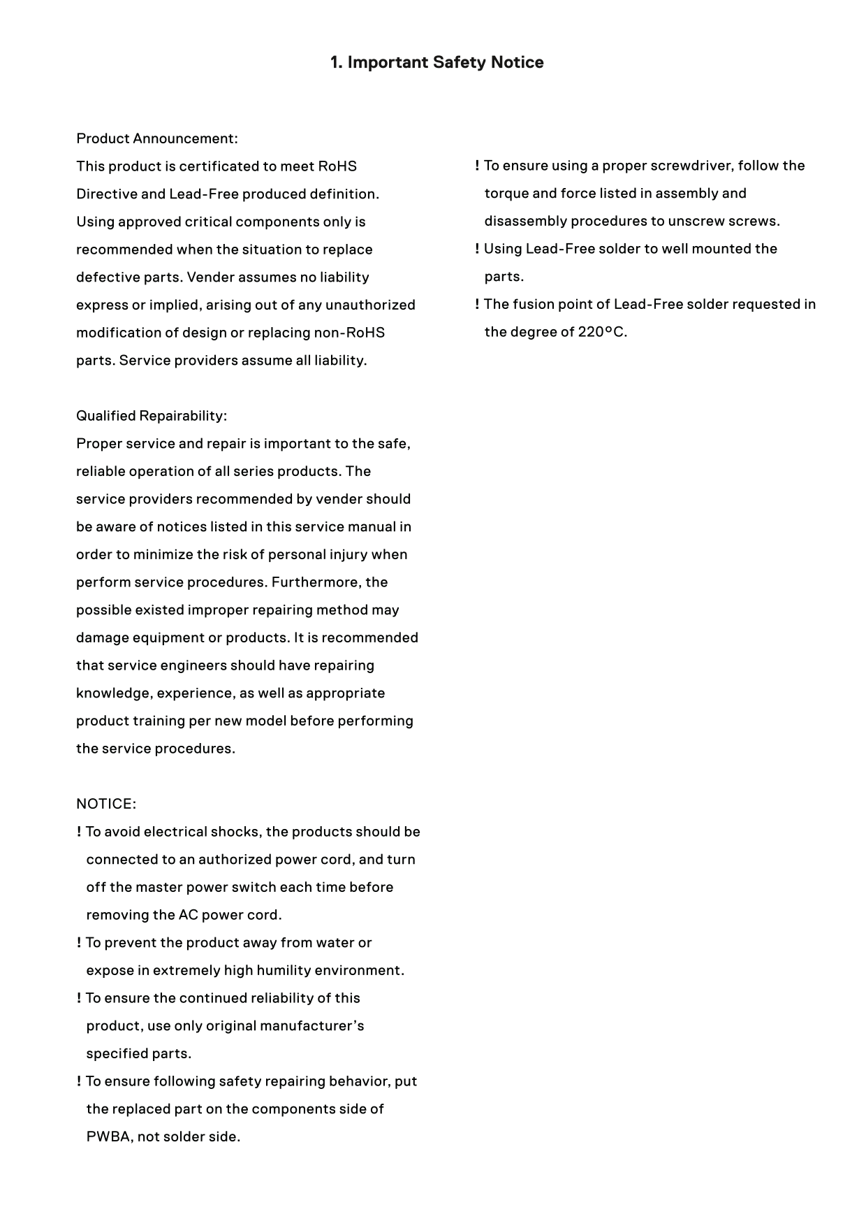
Page 1 Text Content
1. Important Safety Notice
Product Announcement:
This product is certificated to meet Ro HS ! To ensure using a proper screwdriver, follow the Directive and Lead-Free produced definition. torque and force listed in assembly and Using approved critical components only is disassembly procedures to unscrew screws. recommended when the situation to replace ! Using Lead-Free solder to well mounted the defective parts. Vender assumes no liability parts. express or implied, arising out of any unauthorized ! The fusion point of Lead-Free solder requested in modification of design or replacing non-Ro HS the degree of 220°C.
parts. Service providers assume all liability.
Qualified Repairability: Proper service and repair is important to the safe, reliable operation of all series products. The service providers recommended by vender should be aware of notices listed in this service manual in order to minimize the risk of personal injury when perform service procedures. Furthermore, the possible existed improper repairing method may damage equipment or products. It is recommended that service engineers should have repairing knowledge, experience, as well as appropriate product training per new model before performing the service procedures.
NOTICE: ! To avoid electrical shocks, the products should be connected to an authorized power cord, and turn off the master power switch each time before removing the AC power cord. ! To prevent the product away from water or expose in extremely high humility environment. ! To ensure the continued reliability of this product, use only original manufacturer’s specified parts. ! To ensure following safety repairing behavior, put the replaced part on the components side of PWBA, not solder side.
Page Summary Contents For Dell S2421NX Monitor Simplified Service Manual
Manual Details
| Brand | Dell |
|---|---|
| Pages | 14 |
| File Size | 9.21 MB |
| Published | June 24, 2026 |
Enter the captcha to get the download link:

Frequently Asked Questions
How do I fix a monitor image that is too small on screen but does not fill the entire viewing area?
Check the Aspect Ratio setting in the Display menu OSD and reset the monitor to factory settings.
What are the steps to remove the monitor stand base during disassembly?
Place the monitor on a soft cloth, press the stand down to access the release latch, use a long screwdriver to press it, and slide out the assembly.
What safety precautions should be followed when connecting the AC power cord?
Connect to an authorized power cord and turn off the master power switch before removing the cord to avoid electrical shocks.
How can I adjust the OSD controls if they do not appear on the screen?
Turn off the monitor, unplug the power cable, plug it back in, and then turn the monitor on.
What torque specifications should be used for the screws when disassembling the middle bezel?
Use 3~4kgfxcm torque for M3x4 screws (No.1~11) and 1±0.2kgfxcm for M2x3.3 screws (No.12~16).