# A B C D E F G H I J K L M N O P Q R S T U V W X Y Z

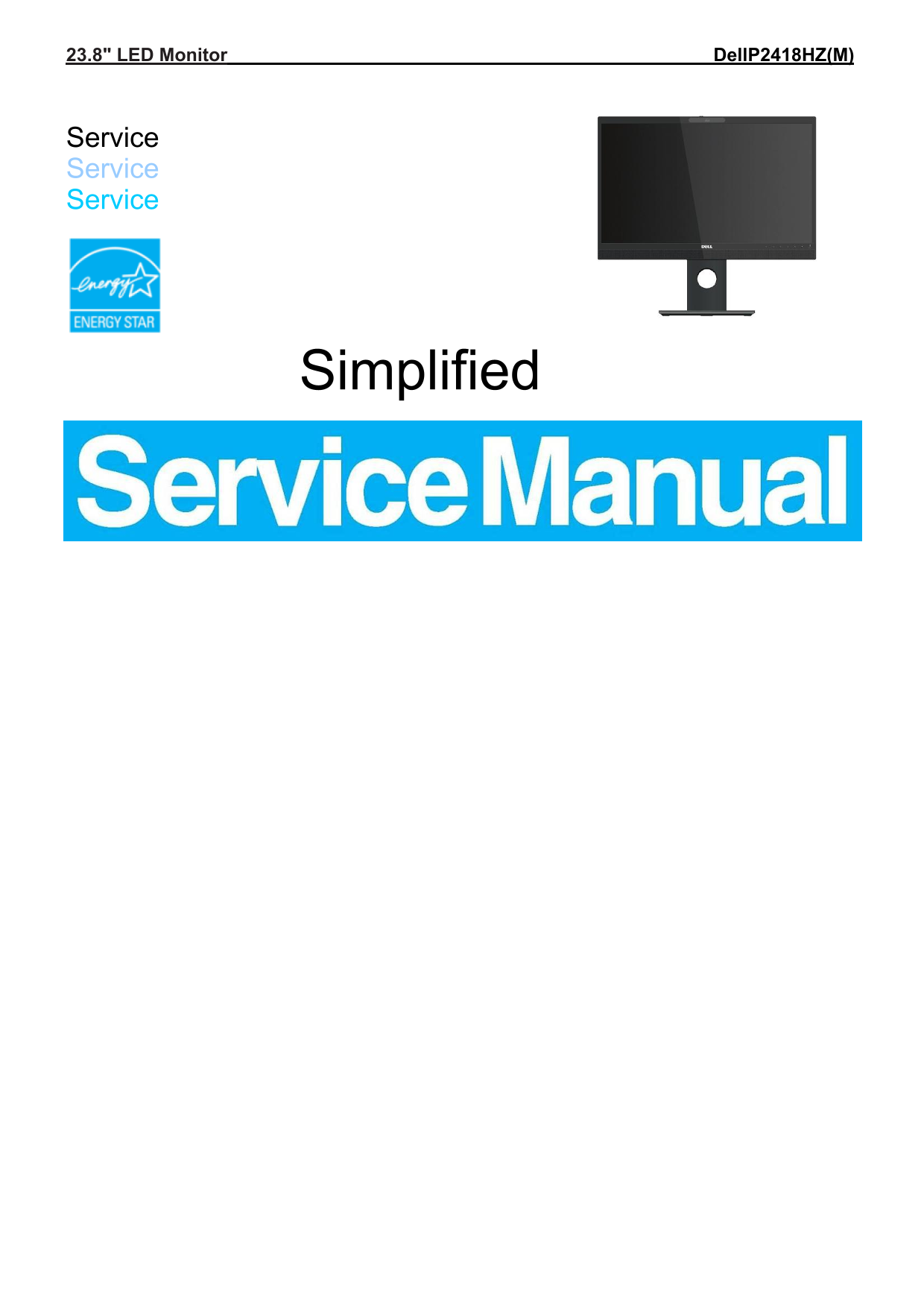
Dell P2418HZ Monitor Simplified Service Manual

Summary

This service manual for the Dell P2418HZ 23.8-inch LED monitor provides important safety notices, exploded view diagrams with complete component parts lists, disassembly and assembly procedures for the front cover, rear cover, main board, power supply board, key board, and stand mechanism. It includes troubleshooting instructions and warnings about using only authorized replacement parts to avoid shock or fire hazards. The manual is intended for qualified Dell service technicians and authorized repair centers responsible for maintaining this video conferencing-optimized monitor with integrated webcam and speakers.
📄 Preview PAGE OF 14

Page 1 Text Content

23.8" LED Monitor Dell P2418HZ(M)

Service Service Service

Simplified

Page Summary Contents For Dell P2418HZ Monitor Simplified Service Manual

Page 1 23.8" LED Monitor Dell P2418HZ(M) Service Service Service Simplified
Page 2 Important Safety Notice Proper service and repair is important to the safe, reliable operation of all DELL Company Equipment. The service procedures recommended by DELL and described in this service m...
Page 3 1. Exploded view diagram with list of items Item Part NO. Description Quantity 1 Q24G0264101 Glass 1 2 A34G4273-VHA1S0100 BEZEL 1 3 A33G2082-VH-1X0100 Latch 1 4 A33G2081-VH-1S0100 COVER_WEBCAM 1 5 A33...
Page 4 24 Q19G5023--1 spring 2 25 Q15G0233--2 KS BKT 1 26 378G060A678YAA00HF SPEAKER 1 27 USBKQ1 USB BOARD 1 28 Q85G0310101 USB shielding 1 29 A34G4274-VH-1S0130 REAR_COVER 1 30 Q37G0686101 Stand 1 31 Q37G06...
Page 5 Tools: 2 Power screwdrivers (φ=5mm, L=60mm); 1 small cross screwdriver; turnbuckle driver; Setting: Power screwdriver torque A=6 kg F.Cm Step Figure TOOl Remark Unscrew the 4 screws by the Philips-hea...
Page 6 Unscrew the screws by the hexagon screwdriver. Torque=6±1kgf.cm Tear out the four wires. Remove the screws by the Philips-head Remove the Screwdriver. Mainboard Torque=6±1kgf.cm Main board
Page 7 Power board Mainframe Remove the screws by the Philips-head Screwdriver. Torque=6±1kgf.cm rear cover Separate the USB board and rear cover. 3.2 Assembly Procedures:
Page 8 Tighten the screws by the Philips-head Assemble Screwdriver. Torque=6±1kgf.cm board and assemble the USB speaker board and speaker Tighten the screws Assemble by the Philips-head the Screwdriver. Main...
Page 9 Tighten the 4 screws by the Assemble Philips-head the rear Screwdriver. cover Torque=6±1kgf.cm Assemble Tighten the screws by the Base ass’y. Philips-head and stand Screwdriver ass’y 4. Trouble shooti...

Manual Details

Brand Dell
Pages 14
File Size 1.84 MB
Published June 23, 2026
5 views

Enter the captcha to get the download link:

captcha

Frequently Asked Questions

What tools are required for disassembly?

Use a power screwdriver (φ=5mm, L=60mm), a small cross screwdriver, and a turnbuckle driver.

What are the safety warnings for this device?

Avoid direct exposure to laser radiation if open. Do not modify the design or use non-original replacement parts.

How should I clean the LCD panel?

Wipe the surface with a soft material only; avoid using dirty or rough cloths.