# A B C D E F G H I J K L M N O P Q R S T U V W X Y Z

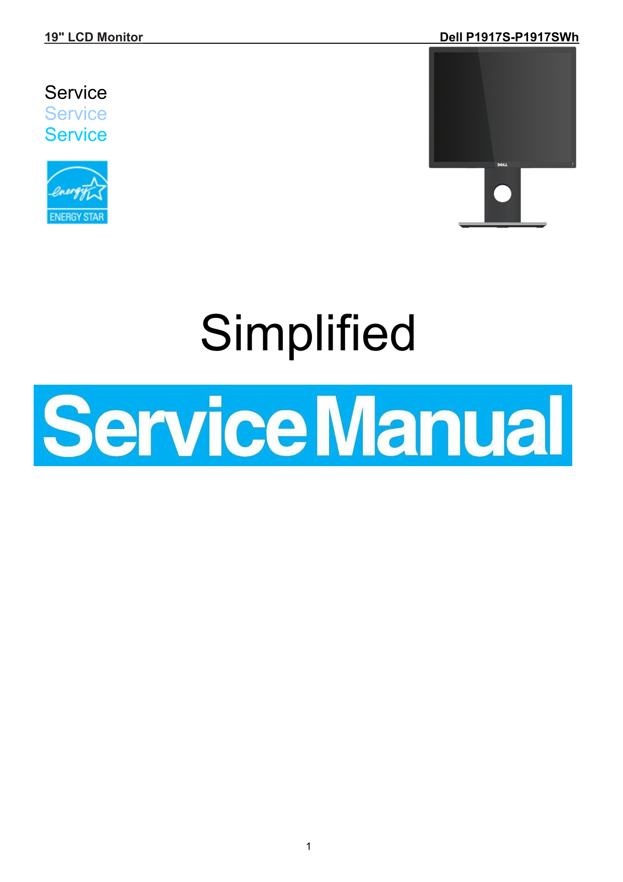
Dell P1917S Monitor Simplified Service Manual

Summary

This is the service manual for the Dell P1917S 19-inch LCD monitor, providing technical documentation for repair and maintenance operations. It includes important safety notices, warnings about laser products, service procedures, and guidelines for using proper tools and replacement parts. The manual emphasizes that only recommended service methods should be used to ensure safety and equipment reliability. It is intended for authorized Dell service technicians and repair professionals.
📄 Preview PAGE OF 20

Page 1 Text Content

19" LCD Monitor Dell P1917S-P1917SWh

Service Service Service

Simplified

Page Summary Contents For Dell P1917S Monitor Simplified Service Manual

Page 1 19" LCD Monitor Dell P1917S-P1917SWh Service Service Service Simplified
Page 2 Important Safety Notice Proper service and repair is important to the safe, reliable operation of all DELL Company Equipment. The service procedures recommended by DELL and described in this service m...
Page 3 1. Exploded view diagram with list of items
Page 4 No. Description Q’ty 1 LOGO DELL 27 1 2 INSULATING SHEET 1 3 BEZEL 1 4 KEY_FUNCTION 1 5 KEY_POWER 1 6 KEY BOARD 1 7 PANEL 1 8 INSULATING SHEET 1 9 ADAPTER BOARD 1 10 INSULATING SHEET 1 11 MAIN BOARD 1...
Page 5 2. Wiring connectivity diagram
Page 6 3. Mechanical Instruction Tools Required List the type and size of the tools that would typically can be used to disassemble the product to a point  where components and materials requiring selective ...
Page 7 3.1 Disassembly Procedures: Step Figure Remark Turn off power, S1.Before Unplug external disassemble cablesfrom product Press the button on the red then pull out the S2. Remove the stand upward, stand...
Page 8 1 2 Use a Philips-head screwdriver to remove 4 screws for unlocking mechanisms. (No.1~4 screw size=M4x10; Torque=12±2kgf.cm) Use Penknife to S3.Remove the separate the bezel and REAR COVER. rear cove ...
Page 9 Disconnect the pins. S4.Remove the USB board Use a Philips-head screwdriver to remove 2 screws for unlocking USB board. (No.1~2 screw size=Q3x4; Torque=4±1kgf.cm) S5.Remove the Use a Philips-head key ...
Page 10 1. Tear down tape in S6. Remove blue. Main fram from 2. Disconnect cable in Panel S7. Remove the Tear out connect in red, Mylar of Power remove the Mylar Board
Page 11 Use a Philips-head screwdriver to remove 6 screws for unlocking Main board and Power board (No.1~5 screw size=D3x6; Torque=6±1kgf.cm S8. Remove the No.6 screw Main and Power size=M4x6; Board Torque=6±...
Page 12 3.2 Assembly Procedures: Step Figure Remark Use a Philips-head screwdriver to screw 6 screws for tighten Main 1 2 board and Power board (No.1~5 screw size=D3x6; Torque=6±1kgf.cm S1. Tighten the No.6 s...
Page 13 S3. Assembly 1. Connect cable in red Main frame 2. Paste tapes in blue. Use a Philips-head S4.Assembly the screwdriver to screw 3 key board screws for tighten key board (No.1~3 screw size=M2x2.5; Torq...
Page 14 Connect the pins. S5.Assembly the USB board Use a Philips-head screwdriver to screw 2 screws for locking USB board. (No.1~2 screw size=Q3x4; Torque=4±1kgf.cm) Connect the pin and paste the black tape ...
Page 15 S7. Assembly the stand
Page 16 4. Trouble shooting instructions

Manual Details

Brand Dell
Pages 20
File Size 5.54 MB
Published June 23, 2026
4 views

Enter the captcha to get the download link:

captcha

Frequently Asked Questions

What tools are needed to disassemble the monitor?

Phillip head screwdriver, hex screwdriver, and penknife.

How do I remove the stand?

Turn off power, unplug cables, press the button on the stand and pull it upward.

What safety precautions should I take when servicing the LCD module?

Mount using corner holes only, avoid pressing the panel edge, use a grounded wristband, and wipe dirt with a soft material.

What are the torque specifications for the main board screws?

Use a hex screwdriver with 4.5±0.5kgf.cm torque for mainboard and 6±1kgf.cm for power and main boards.