Vishay TFBS4711 User Guide
Summary
This low-profile Infrared Data Transceiver is an advanced front-end solution utilizing PIN photodiode and IRED technology for robust IrDA communication up to 115.2 kbit/s. The module ensures reliable performance with constant output pulse widths, extended range (up to 1m), and ultra-low power draw in standby mode. This documentation details its full operational specifications, applications in battery-powered devices, data loggers, medical equipment, and POS systems. Ideal for engineers requiring a compact, highly efficient solution compliant with modern standards.
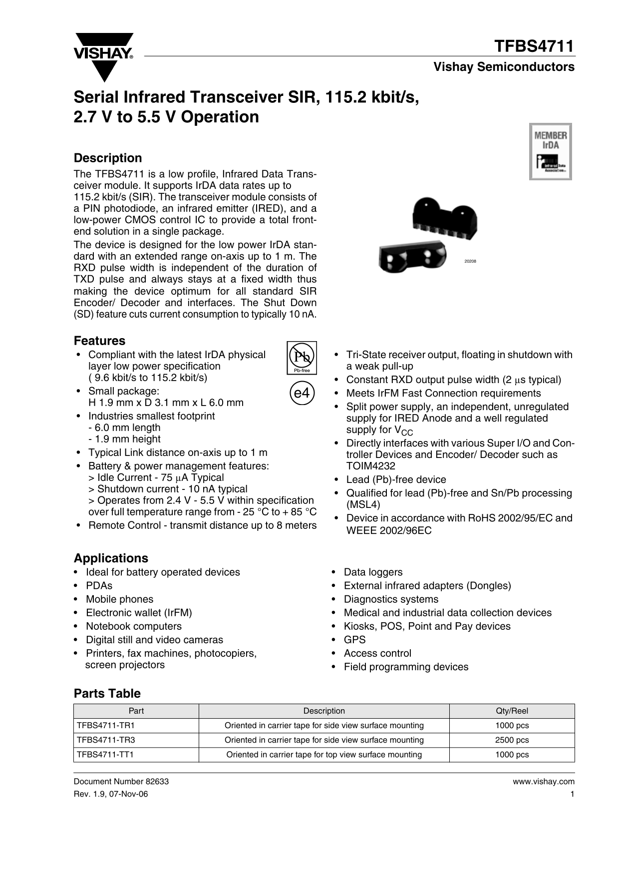
Page 1 Text Content
TFBS4711 Vishay Semiconductors
Serial Infrared Transceiver SIR, 115.2 kbit/s, 2.7 V to 5.5 V Operation
Description The TFBS4711 is a low profile, Infrared Data Trans- ceiver module. It supports Ir DA data rates up to 115.2 kbit/s (SIR). The transceiver module consists of a PIN photodiode, an infrared emitter (IRED), and a low-power CMOS control IC to provide a total front- end solution in a single package. The device is designed for the low power Ir DA stan- dard with an extended range on-axis up to 1 m. The RXD pulse width is independent of the duration of TXD pulse and always stays at a fixed width thus making the device optimum for all standard SIR Encoder/ Decoder and interfaces. The Shut Down (SD) feature cuts current consumption to typically 10 n A.
Features
Compliant with the latest Ir DA physical Tri-State receiver output, floating in shutdown with layer low power specification a weak pull-up
( 9.6 kbit/s to 115.2 kbit/s) Constant RXD output pulse width (2 µs typical) Small package: e4 Meets Ir FM Fast Connection requirements H 1.9 mm x D 3.1 mm x L 6.0 mm
Split power supply, an independent, unregulated
Industries smallest footprint supply for IRED Anode and a well regulated - 6.0 mm length supply for VCC - 1.9 mm height
Directly interfaces with various Super I/O and Con-
Typical Link distance on-axis up to 1 m troller Devices and Encoder/ Decoder such as Battery & power management features: TOIM4232 > Idle Current - 75 µA Typical Lead (Pb)-free device > Shutdown current - 10 n A typical
Qualified for lead (Pb)-free and Sn/Pb processing
> Operates from 2.4 V - 5.5 V within specification
(MSL4)
over full temperature range from - 25 °C to + 85 °C
Device in accordance with Ro HS 2002/95/EC and
Remote Control - transmit distance up to 8 meters
WEEE 2002/96EC
Applications
• Ideal for battery operated devices • Data loggers • PDAs • External infrared adapters (Dongles) • Mobile phones • Diagnostics systems • Electronic wallet (Ir FM) • Medical and industrial data collection devices • Notebook computers • Kiosks, POS, Point and Pay devices • Digital still and video cameras • GPS • Printers, fax machines, photocopiers, • Access control
screen projectors • Field programming devices
Parts Table
Part Description Qty/Reel
TFBS4711-TR1 Oriented in carrier tape for side view surface mounting 1000 pcs TFBS4711-TR3 Oriented in carrier tape for side view surface mounting 2500 pcs
TFBS4711-TT1 Oriented in carrier tape for top view surface mounting 1000 pcs
Document Number 82633 www.vishay.com Rev. 1.9, 07-Nov-06
Page Summary Contents For Vishay TFBS4711 User Guide
Manual Details
| Brand | Vishay |
|---|---|
| Pages | 12 |
| File Size | 201.59 KB |
| Published | July 16, 2026 |
Enter the captcha to get the download link:

Frequently Asked Questions
What are the primary operating standards supported?
It supports IrDA data rates up to 115.2 kbit/s, compliant with the latest IrDA physical layer and also includes SIR, MIR, and FIR modes.
How does the device enter a low-power state?
It can operate over a full temperature range from -25 °C to +85 °C ambient.
Does it require continuous power for the IR emitter?
No, you can use a separate unregulated power supply directly at Pin 1 (IRED Anode).