Vishay SFH690ABT AT BT CT Data Sheet
Summary
This optocoupler series is designed for robust signal transmission and high electrical isolation between separated circuits, ideal for demanding PCB and industrial control systems (PLCs, Telecom). The manual provides detailed specifications—including coupling ratios, thermal characteristics, and switching parameters—allowing engineers to properly integrate this Mini-Flat package device into their electronic designs.
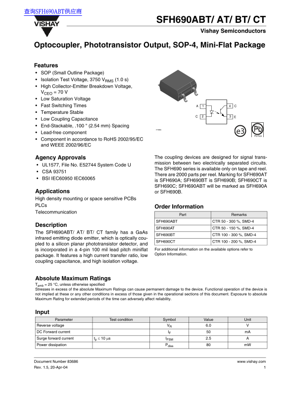
Page 1 Text Content
查询SFH690ABT供应商
SFH690ABT/ AT/ BT/ CT
Vishay Semiconductors
Optocoupler, Phototransistor Output, SOP-4, Mini-Flat Package
Features SOP (Small Outline Package) Isolation Test Voltage, 3750 VRMS (1.0 s) High Collector-Emitter Breakdown Voltage, VCEO = 70 V Low Saturation Voltage Fast Switching Times CA Temperature Stable Low Coupling Capacitance End-Stackable, .100 " (2.54 mm) Spacing
i179065 Pb
Lead-free component e3 Pb-free
Component in accordance to Ro HS 2002/95/EC and WEEE 2002/96/EC
Agency Approvals The coupling devices are designed for signal trans- mission between two electrically separated circuits.
UL1577, File No. E52744 System Code U
The SFH690 series is available only on tape and reel.
CSA 93751
There are 2000 parts per reel. Marking for SFH690AT
BSI IEC60950 IEC60065
is SFH690A; SFH690BT is SFH690B; SFH690CT is SFH690C; SFH690ABT will be marked as SFH690A
Applications or SFH690B. High density mounting or space sensitive PCBs PLCs
Order Information
Telecommunication
Part Remarks
SFH690ABT CTR 50 - 300 %, SMD-4
Description
SFH690AT CTR 50 - 150 %, SMD-4
The SFH690ABT/ AT/ BT/ CT family has a Ga As
SFH690BT CTR 100 - 300 %, SMD-4
infrared emitting diode emitter, which is optically cou-
SFH690CT CTR 100 - 200 %, SMD-4
pled to a silicon planar phototransistor detector, and
is incorporated in a 4-pin 100 mil lead pitch miniflat For additional information on the available options refer to Option Information.
package. It features a high current transfer ratio, low coupling capacitance, and high isolation voltage.
Absolute Maximum Ratings Tamb = 25 °C, unless otherwise specified Stresses in excess of the absolute Maximum Ratings can cause permanent damage to the device. Functional operation of the device is not implied at these or any other conditions in excess of those given in the operational sections of this document. Exposure to absolute Maximum Rating for extended periods of the time can adversely affect reliability.
Input Parameter Test condition Symbol Value Unit
Reverse voltage VR 6.0
DC Forward current IF m A Surge forward current tp ≤ 10 µs IFSM 2.5 Power dissipation Pdiss m W
Document Number 83686 www.vishay.com Rev. 1.5, 20-Apr-04
Page Summary Contents For Vishay SFH690ABT AT BT CT Data Sheet
Manual Details
| Brand | Vishay |
|---|---|
| Pages | 7 |
| File Size | 132.58 KB |
| Published | June 03, 2026 |
Enter the captcha to get the download link:

Frequently Asked Questions
What is the specified isolation test voltage rating?
The isolation test voltage between emitter and detector is 3750 V RMS (1.0 s).
Is the component compliant with environmental standards?
Yes, it is lead-free (Pb-free) and complies with RoHS and WEEE directives.
What are the acceptable operating temperature ranges?
The ambient operating temperature range is -55 to +100 °C, for a storage temperature range of -55 to +150 °C.
Must I validate this part before using it in my design?
Yes, all operating parameters must be validated by the customer for each specific application.