# A B C D E F G H I J K L M N O P Q R S T U V W X Y Z

Texas Instruments PCM3501 Data Handbook/Specifications

Summary

The PCM3501 is an integrated, low-cost 16-bit voice/modem CODEC designed for demanding audio applications and embedded systems. This single chip integrates vital functions—including ADCs, DACs, anti-aliasing filters, and digital signal processors—onto one serial bus, simplifying design considerably. The manual provides comprehensive specifications detailing its high performance (88dB dynamic range) and ultra-low power consumption, making it ideal for use in portable voice recorders, PDAs, set-top boxes, and teleconferencing equipment requiring reliable connectivity.
📄 Preview PAGE OF 25

Page 1 Text Content

PCM PCM3501®

Low Voltage, Low Power, 16-Bit, Mono

VOICE/MODEM CODEC

FEATURES POWER-DOWN MODE: 60µA (typ) SINGLE +2.7V TO +3.6V POWER SUPPLY

16-BIT DELTA-SIGMA DAC AND ADC

SMALL PACKAGE: 24-Lead SSOP

DIFFERENTIAL INPUT AND OUTPUT DESIGNED FOR MODEM ANALOG FRONT END:

Supports up to 56kbps Operation APPLICATIONS

ANALOG PERFORMANCE:

SOFTWARE MODEMS FOR:

Sampling Frequency: 7.2k Hz to 26k Hz

Personal Digital Assistant

Dynamic Range: 88d B (typ) at f S = 8k Hz, f IN = 1k Hz

Notebook and Hand-Held PCs

SYSTEM CLOCK: 512f S

Set-Top Box

MASTER OR SLAVE OPERATION Digital Television

ON-CHIP CRYSTAL OSCILLATOR CIRCUIT Embedded Systems

ADC-TO-DAC LOOP-BACK MODE PORTABLE VOICE RECORDER/PLAYER TIME SLOT MODE SUPPORTS UP TO SPEECH RECOGNITION/SYNTHESIS FOUR CODECs ON A SINGLE SERIAL

TELECONFERENCING PRODUCTS

INTERFACE

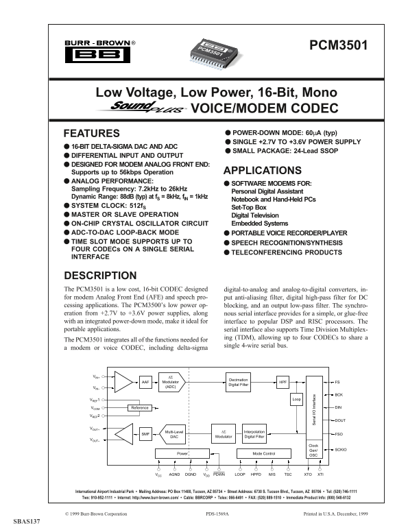
DESCRIPTION The PCM3501 is a low cost, 16-bit CODEC designed digital-to-analog and analog-to-digital converters, in- for modem Analog Front End (AFE) and speech pro- put anti-aliasing filter, digital high-pass filter for DC cessing applications. The PCM3500’s low power op- blocking, and an output low-pass filter. The synchro- eration from +2.7V to +3.6V power supplies, along er ia l I /O In te rf ac nous serial interface provides for a simple, or glue-free with an integrated power-down mode, make it ideal for interface to popular DSP and RISC processors. The portable applications. serial interface also supports Time Division Multiplex-

ing (TDM), allowing up to four CODECs to share a

The PCM3501 integrates all of the functions needed for

single 4-wire serial bus.

a modem or voice CODEC, including delta-sigma

VIN+ ∆Σ

Decimation

AAF Modulator HPF FS

Digital Filter

VIN– (ADC)

VREF1 Loop

VCOM Reference DIN

VREF2

VOUT+

Multi-Level ∆Σ Interpolation

SMF FSO

DAC Modulator Digital Filter

VOUT–

Clock

Gen/ SCKIO

Power Mode Control

DGNDAGND VDDVCC PDWN M/SHPFD TSC XTIXTOLOOP

International Airport Industrial Park • Mailing Address: PO Box 11400, Tucson, AZ 85734 • Street Address: 6730 S. Tucson Blvd., Tucson, AZ 85706 • Tel: (520) 746-1111 Twx: 910-952-1111 • Internet: http://www.burr-brown.com/ • Cable: BBRCORP • Telex: 066-6491 • FAX: (520) 889-1510 • Immediate Product Info: (800) 548-6132

© 1999 Burr-Brown Corporation PDS-1569A Printed in U.S.A. December, 1999 PCM3501

SBAS137

Page Summary Contents For Texas Instruments PCM3501 Data Handbook/Specifications

Page 1 PCM PCM3501® Low Voltage, Low Power, 16-Bit, Mono VOICE/MODEM CODEC FEATURES POWER-DOWN MODE: 60µA (typ) SINGLE +2.7V TO +3.6V POWER SUPPLY 16-BIT DELTA-SIGMA DAC AND ADC SMALL PACKAGE: 24-Lead SSOP D...
Page 2 SPECIFICATIONS All specifications at TA = +25°C, VDD = VCC = 3.3V, f S = 8k Hz, and nominal system clock (XTI) = 512f S, and differntial input and output mode, unless otherwise noted. Measurement band...
Page 3 ABSOLUTE MAXIMUM RATINGS ELECTROSTATIC Supply Voltage, +VDD, +VCC (1) +6.5V DISCHARGE SENSITIVITY Supply Voltage Differences(2) ±0.1V GND Voltage Differences(3) ±0.1V This integrated circuit can be da...
Page 4 PIN CONFIGURATION Top View SSOP PCM3501 VCOM VCC VREF1 AGND VREF2 VOUT+ VIN+ VOUT– VIN– PDWN M/S LOOP TSC HPFD BCK XTI FS XTO DIN SCKIO DOUT DGND FSO VDD PIN ASSIGNMENTS PIN NAME I/O DESCRIPTION VCOM ...
Page 5 TYPICAL PERFORMANCE CURVES pl itu de d B DAC SECTION pl itu de d B DIGITAL FILTER INTERPOLATION FILTER INTERPOLATION FILTER FREQUENCY RESPONSE PASSBAND RIPPLE CHARACTERISTICS Normalized Frequency (• f...
Page 6 d B pl itu de d B TYPICAL PERFORMANCE CURVES (Cont.) TA = +25°C, VCC = VDD = +3.3V, f S = 8k Hz, and f SIGNAL = 1k Hz, unless otherwise specified. DAC SECTION DAC OUTPUT SPECTRA DAC OUTPUT SPECTRUM (–...
Page 7 TYPICAL PERFORMANCE CURVES (Cont.) DAC SECTION t – 0d d B t – 0d d B t – 0d d B DAC CHARACTERISTICS vs TEMPERATURE, SUPPLY, AND SAMPLING FREQUENCY TOTAL HARMONIC DISTORTION + NOISE DYNAMIC RANGE AND S...
Page 8 pl itu de d B pl itu de d B TYPICAL PERFORMANCE CURVES pl itu de d B ADC SECTION DIGITAL FILTER DECIMATION FILTER DECIMATION FILTER FREQUENCY RESPONSE STOPBAND ATTENUATION CHARACTERISTICS 0.2 0.4 0.6 ...
Page 9 TYPICAL PERFORMANCE CURVES (Cont.) TA = +25°C, VCC = VDD = +3.3V, f S = 8k Hz, and f SIGNAL = 1k Hz, unless otherwise specified. pl itu de d B ADC SECTION pl itu de d B ANALOG FILTER ANTI-ALIASING FIL...
Page 10 TYPICAL PERFORMANCE CURVES (Cont.) t – 0. 5d d B TA = +25°C, VCC = VDD = +3.3V, f S = 8k Hz, and f SIGNAL = 1k Hz, unless otherwise specified. ADC SECTION ADC CHARACTERISTICS vs TEMPERATURE, SUPPLY AN...
Page 11 TYPICAL PERFORMANCE CURVES (Cont.) TA = +25°C, VCC = VDD = +3.3V, f S = 8k Hz, and f SIGNAL = 1k Hz, unless otherwise specified. , I nd SUPPLY CURRENT vs SUPPLY VOLTAGE AND SAMPLING FREQUENCY ICC, IDD...
Page 12 SYSTEM CLOCK AND RESET/ SAMPLING FREQUENCY (k Hz) SYSTEM CLOCK FREQUENCY (MHz) POWER DOWN SYSTEM CLOCK INPUT AND OUTPUT The PCM3501 requires a system clock for operating the digital filters and delta-...
Page 13 Reset and Power Down PDWN causes the reset initialization sequence to start. During the initialization sequence, the DAC output is forced The PCM3501 supports power-on reset, external reset, and to AG...
Page 14 SERIAL INTERFACE anteed in Master Mode). Data for DIN is clocked into the serial interface on the rising edge of BCK, while data for The serial interface of the PCM3501 is a 4-wire synchronous DOUT is...
Page 15 t FSP t FSW 0.5VDD (output) t CKFS t BCKP 0.5VDD (output) t BCKH t BCKL 0.5VDD (input) t DISU t DIHD 0.5VDD (output) t CKDO NOTES: Timing measurement reference level is (VIH/VIL)/2. Rising and falling...
Page 16 SYNCHRONIZATION REQUIREMENTS interface bus. This is useful for system applications that require multiple modem or voice channels. Figure 11 shows The PCM3501 requires that FS and BCK be synchronous ex...
Page 17 One Frame = 1/f S, 64 Bits per Frame, 16 Bits per Slot CODEC A CODEC B CODEC C CODEC D Slot 0, 16 Bits Slot 1, 16 Bits Slot 2, 16 Bits Slot 3, 16 Bits FS (A) FSO (A) FS (B) FSO (B) FS (C) FSO (C) FS (...
Page 18 Table III shows the TSC pin settings and corresponding LOOP (PIN 19) LOOP-BACK MODE mode selections. When Time Slot Mode is enabled, FSO Loop-Back Mode Disabled, Normal Operation (pin 12) is used as a...
Page 19 t FSP t FSW FS pl itu de d B 0.5VDD (output) t BCKP t CKFS 0.5VDD (output) t BCKL t BCKH 0.5VDD (input) t DISU t DIHD High Impedance DOUT High Impedance 0.5VDD (output) t CKDOt HZDO t DOHZ 0.5VDD (out...
Page 20 unbuffered on pin 1 for decoupling. A 1µF to 10µF alumi- APPLICATIONS INFORMATION num electrolytic or tantalum capacitor is recommended for BASIC CIRCUIT CONNECTIONS decoupling purposes. This capacito...
Page 21 VREF1 (pin 2) and VREF2 (pin 3) are reference voltages used by a split ground plane, with the PCM3501 positioned by the delta-sigma modulators. They are brought out strictly entirely over the analog s...
Page 22 OUTPUT FILTER CIRCUITS FOR THE DAC noise requirements for a particular system. Generally, a 2nd- order or better low-pass circuit will be required, with the pl itu de d B The PCM3501’s DAC uses delta-...
Page 23 The AFE circuit consists of a buffer/filter for each input of THEORY OF OPERATION the converter. The frequency response for the filter is shown in Figure 22. Since the delta-sigma modulator oversample...
Page 24 shaper consists of five integrators which use a switched- DAC SECTION capacitor topology, a comparator, and a feedback loop con- The delta-sigma DAC section of PCM3501 is based on a 5- sisting of a on...
Page 25 IMPORTANT NOTICE Texas Instruments and its subsidiaries (TI) reserve the right to make changes to their products or to discontinue any product or service without notice, and advise customers to obtain...

Manual Details

Brand Texas Instruments
Pages 25
File Size 189.38 KB
Published June 21, 2026
14 views

Enter the captcha to get the download link:

captcha

Frequently Asked Questions

What required voltage range can the PCM3501 operate on?

It supports a single +2.7V to +3.6V power supply.

How many CODECs can be shared via the serial interface?

The serial interface supports Time Division Multiplexing (TDM), allowing up to four CODECs.

What is the typical dynamic range performance of the unit?

It offers a dynamic range of 88dB (typ) at f = 8kHz and f = 1kHz.

What is the current draw in power-down mode?

In Power-Down Mode, the typical power consumption is 60μA.