Texas Instruments Extending the Common-Mode Range of Difference Amplifiers Data Sheet User's Guide
Summary
This technical bulletin provides advanced design solutions for maximizing and extending the operational common-mode input range in precision difference amplifiers. It details proven techniques, including fixed offsetting and dynamic voltage boosting methods, allowing component use with reduced or variable power supplies. This guide is essential reading for analog circuit designers and engineers who are building high-precision measurement systems, sensor interfaces, or industrial applications that require an exceptionally wide signal voltage swing (common-mode range).
Page 1 Text Content
APPLICATION BULLETIN® Mailing Address: PO Box 11400 • Tucson, AZ 85734 • Street Address: 6730 S. Tucson Blvd. • Tucson, AZ 85706 Tel: (602) 746-1111 • Twx: 910-952-111 • Telex: 066-6491 • FAX (602) 889-1510 • Immediate Product Info: (800) 548-6132 EXTENDING THE COMMON-MODE RANGE OF DIFFERENCE AMPLIFIERS
By R. Mark Stitt (602) 746-7445
Extending the common-mode range of difference amplifiers OFFSETTING THE INPUT COMMON-MODE allows their use in a wider variety of reduced power-supply RANGE WITH A CONSTANT VOLTAGE applications.
In many applications, the common-mode signal range is
The INA117 has a specified common-mode input range of known and the common-mode input range of the difference ±200V when operating on standard ±15V power supplies. At amplifier can be adjusted to coincide with the required power-supply voltages above ±13V, the INA117 input range range. For example, the ±60V common-mode range of the is limited to ±200V by the power capabilities of its internal INA117 operating on ±6V supplies could be shifted to range input resistors. On reduced power supplies, the input range from +0V to +120V, or +50V to +170V. is limited by the common mode input range of the internal
To offset the common-mode range, the reference connection
op amp.
of the difference amplifier is connected to an offsetting
The linear common-mode input range of the internal op amp voltage, V , instead of ground. With the reference connected
extends to within 3V of its power supply voltage. For to an offsetting potential, a second difference amplifier must example, with a ±15V power supply, the common-mode be used to refer the output back to ground.
input range of the internal op amp is ±12V. Because the
One way to offset the input voltage is to connect the
INA117 internal resistor network divides the input by 20, the
reference pins 1 and 5 to the negative supply voltage as
actual input range of the INA117 would be 20 • (±12V), or
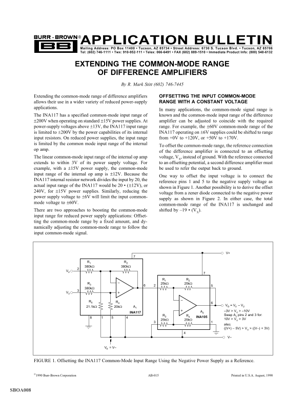
shown in Figure 1. Another possibility is to derive the offset
240V, for ±15V power supplies. Similarly, reducing the
voltage from a zener diode connected to the negative power
power supply voltage to ±6V will limit the input common-
supply as shown in Figure 2. In either case, the total
mode voltage to ±60V.
common-mode range of the INA117 is unchanged and There are two approaches to boosting the common-mode shifted by –19 • (V
input range for reduced power supply applications: Offset- ting the common-mode range by a fixed amount, and dy- namically adjusting the common-mode range to follow the input common-mode signal.
V = V – VO 3 2
A2 –3V > VO > –10V
INA117
R3 R4 Swap A2 pins 2 and 3 for:
INA105
25kΩ 25kΩ 10V > VO > 3V also; ((V+) – 5V) > VO > ((V–) + 3V)
FIGURE 1. Offsetting the INA117 Common-Mode Input Range Using the Negative Power Supply as a Reference.
AB-0151990 Burr-Brown Corporation AB-015 Printed in U.S.A. August, 1990
SBOA008
Page Summary Contents For Texas Instruments Extending the Common-Mode Range of Difference Amplifiers Data Sheet User's Guide
Manual Details
| Brand | Texas Instruments |
|---|---|
| Pages | 6 |
| File Size | 49.20 KB |
| Published | May 28, 2026 |
Enter the captcha to get the download link:

Frequently Asked Questions
What is the common-mode input range without modifications?
The INA117 has a specified common-mode input range of ±200V when running on standard ±15V power supplies.
How can I extend the common-mode range using an offset voltage?
Connect the reference connection to an offsetting potential, V, instead of ground. This shifts the range while keeping the INA117's total common-mode voltage unchanged.
What is used to dynamically adjust/boost the common-mode input range?
The common-mode range can be boosted by driving the reference connection dynamically in response to changes using an auxiliary amplifier and appropriate resistors (R, R, R).
Are there inherent limitations when operating on reduced power supplies?
Yes, common-mode ranges are limited by the internal op amp's common mode input range on reduced supplies. For instance, ±6V supplies may shift the INA117's range to 20 • (±12V).