ROHM EMY1 UMY1N FMY1A Data Handbook(1)(1)User Manual
Summary
Designed for complex interface and driver circuits, these digital transistors offer an advanced, compact solution by integrating two chips within one package and adding built-in 47kW bias resistors. This unique architecture simplifies circuit design, allowing easy inverter configuration with high isolation and eliminated parasitic effects. The comprehensive datasheet serves as a resource for engineers, providing detailed specifications on absolute maximum ratings, electrical characteristics (including I_on/I_off), transfer curves, and precise SMT packaging dimensions, ensuring reliable integration into demanding digital applications.
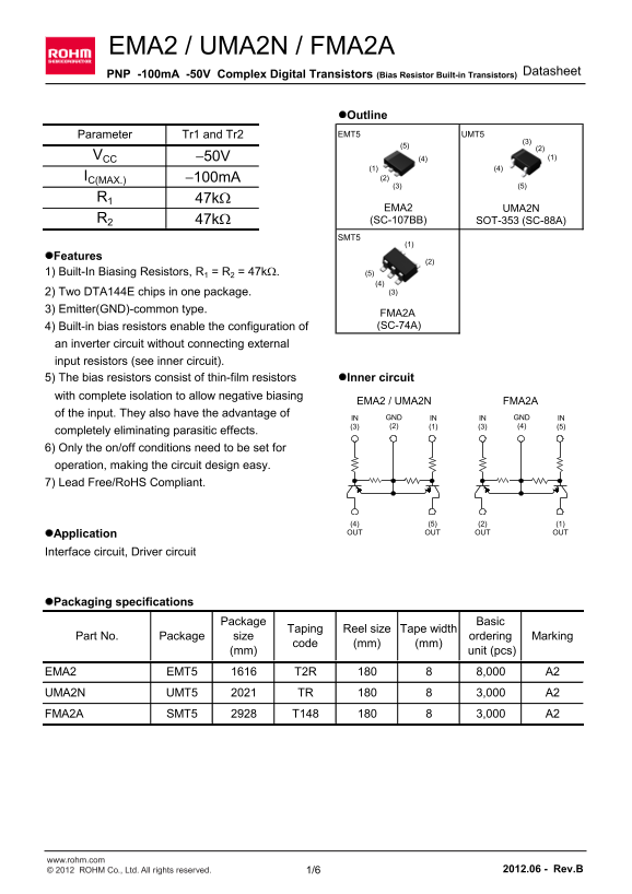
Page 1 Text Content
EMA2 / UMA2N / FMA2A
Datasheet
PNP -100m A -50V Complex Digital Transistors (Bias Resistor Built-in Transistors)
l Outline Parameter Tr1 and Tr2 EMT5 UMT5
VCC -50V (4) (1)
IC(MAX.) -100m A (2) (3) (5)
EMA2 UMA2N
R2 47k W (SC-107BB) SOT-353 (SC-88A)
l Features
1) Built-In Biasing Resistors, R1 = R2 = 47k W. (5)
(4) 2) Two DTA144E chips in one package. (3)
3) Emitter(GND)-common type.
FMA2A 4) Built-in bias resistors enable the configuration of (SC-74A)
an inverter circuit without connecting external input resistors (see inner circuit).
5) The bias resistors consist of thin-film resistors l Inner circuit
with complete isolation to allow negative biasing
EMA2 / UMA2N FMA2A
of the input. They also have the advantage of
IN GND IN IN GND IN (3) (2) (1) (3) (4) (5)
completely eliminating parasitic effects. 6) Only the on/off conditions need to be set for operation, making the circuit design easy. 7) Lead Free/Ro HS Compliant.
(4) (5) (2) (1) l Application OUT OUT OUT OUT
Interface circuit, Driver circuit
l Packaging specifications
Package Basic
Taping Reel size Tape width
Part No. Package size ordering Marking
code (mm) (mm)
(mm) unit (pcs)
EMA2 EMT5 T2R 8,000 A28 UMA2N UMT5 TR 3,000 A2 FMA2A SMT5 T148 3,000 A2
www.rohm.com © 2012 ROHM Co., Ltd. All rights reserved. 1/6 2012.06 - Rev.B
Page Summary Contents For ROHM EMY1 UMY1N FMY1A Data Handbook(1)(1)User Manual
Manual Details
| Brand | ROHM |
|---|---|
| Pages | 7 |
| File Size | 623.79 KB |
| Published | June 19, 2026 |
Enter the captcha to get the download link:

Frequently Asked Questions
What is the recommended connection method for the input circuit?
The device uses an Emitter(GND)-common type design and has built-in biasing resistors that allow the configuration of an inverter circuit without external input resistors.
What are the power dissipation limits for this transistor?
For EMA2/UMA2N, the total power dissipation is 150 mW. For FMA2A, it is 300 mW.
Can these transistors be used in safety-critical applications (e.g., medical or aerospace)?
No, they are not designed for use with equipment requiring an extremely high level of reliability, such as medical instruments or transportation equipment.
What is the maximum achievable transition frequency reported?
The data sheet lists a transition frequency (f) up to 250 MHz.
Are these components compliant with environmental standards like RoHS?
Yes, the transistors specified in this document are lead-free and RoHS compliant.