ROHM EMF8 Data Sheet and Manual
Summary
The EMF8 Transistor package provides a highly efficient dual-transistor solution for integrated power management circuits. This single unit combines two independent transistors into one compact EMT6 shell, dramatically reducing mounting costs and physical area for power switching applications. The accompanying manual delivers comprehensive technical data required by engineers, including absolute maximum ratings, detailed electrical characteristics (like gain and breakdown voltages), transition frequencies ($f_T$), and performance curves crucial for robust circuit design across diverse operating conditions.
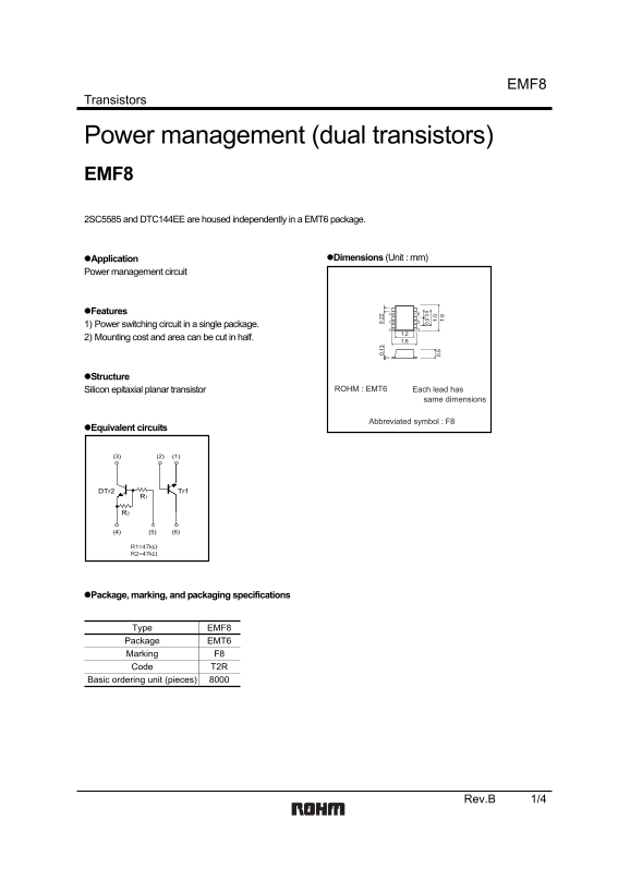
Page 1 Text Content
Transistors
Power management (dual transistors) EMF8 2SC5585 and DTC144EE are housed independently in a EMT6 package.
Application Dimensions (Unit : mm)
Power management circuit
Features (4) (3)
1) Power switching circuit in a single package.
2) Mounting cost and area can be cut in half.
Structure
Silicon epitaxial planar transistor ROHM : EMT6 Each lead has
same dimensions
Abbreviated symbol : F8
Equivalent circuits 0. 0. 1.
DTr2 Tr1
Package, marking, and packaging specifications
Type EMF8 Package EMT6 Marking F8 Code T2R
Basic ordering unit (pieces)
Rev.B 1/4
Page Summary Contents For ROHM EMF8 Data Sheet and Manual
Manual Details
| Brand | ROHM |
|---|---|
| Pages | 5 |
| File Size | 83.80 KB |
| Published | June 18, 2026 |
Enter the captcha to get the download link:

Frequently Asked Questions
Can I use this component in life-critical systems like medical instruments?
No. For equipment requiring extremely high reliability, such as aerospace machinery or medical instruments, consult a sales representative first.
What is the maximum power dissipation limit per single element?
The total power dissipation (PC) is 150mW, but each individual element must not exceed 120mW.
What preventative measures should I take when integrating this transistor package?
You must account for derating characteristics and implement sufficient safety features, such as anti-flammability and fail-safe measures, in your design.