ROHM EMD3 User Guide UMD3N IMD3A Owner's Manual
Summary
These dual digital transistors are designed for compact, high-reliability electronic applications. Available in multiple surface-mount packages, they feature independent elements to minimize signal interference while significantly reducing board area and mounting costs. The comprehensive manual provides critical engineering data, including absolute maximum ratings, detailed electrical specifications (VI/IO characteristics), packaging codes, and full operating curves for both NPN and PNP types. This component is ideal for engineers developing robust electronic devices such as communication equipment and automated systems requiring stable, high-performance switching components.
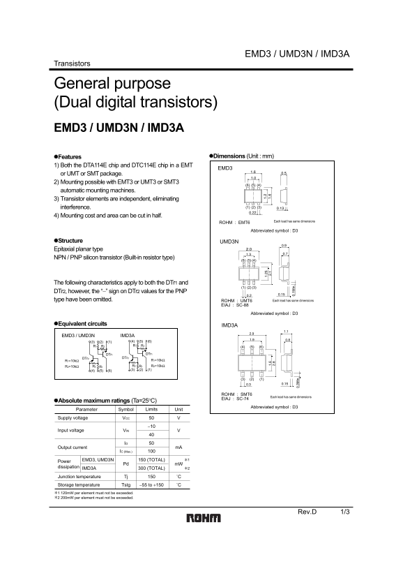
Page 1 Text Content
EMD3 / UMD3N / IMD3A
Transistors
General purpose (Dual digital transistors) EMD3 / UMD3N / IMD3A
Features Dimensions (Unit : mm)
1) Both the DTA114E chip and DTC114E chip in a EMT
or UMT or SMT package. 2) Mounting possible with EMT3 or UMT3 or SMT3
automatic mounting machines. 3) Transistor elements are independent, eliminating
interference. (1) (2) (3)
4) Mounting cost and area can be cut in half.
Each lead has same dimensions
ROHM : EMT6
Abbreviated symbol : D3
Structure UMD3N Epitaxial planar type NPN / PNP silicon transistor (Built-in resistor type)
The following characteristics apply to both the DTr1 and
DTr2, however, the “−” sign on DTr2 values for the PNP type have been omitted. ROHM : UMT6 Each lead has same dimensions
EIAJ : SC-88
Abbreviated symbol : D3
Equivalent circuits IMD3A
EMD3 / UMD3N IMD3A
DTr1 DTr1
DTr2 DTr2
ROHM : SMT6
Each lead has same dimensions
EIAJ : SC-74
Absolute maximum ratings (Ta=25°C)
Abbreviated symbol : D3
Parameter Symbol Limits Unit
Supply voltage VCC
Input voltage VVIN
Output current m A
IC (Max.)
EMD3, UMD3N 150 (TOTAL) ∗1
Power
Pd m W
dissipation
IMD3A 300 (TOTAL) ∗2
Junction temperature Tj ˚C
Storage temperature Tstg −55 to +150 ˚C
∗1 120m W per element must not be exceeded. ∗2 200m W per element must not be exceeded.
Rev.D 1/3
Page Summary Contents For ROHM EMD3 User Guide UMD3N IMD3A Owner's Manual
Manual Details
| Brand | ROHM |
|---|---|
| Pages | 4 |
| File Size | 98.52 KB |
| Published | June 20, 2026 |
Enter the captcha to get the download link:

Frequently Asked Questions
What is the maximum permissible power dissipation for one element?
The junction temperature must not exceed 150°C, and 200mW per element must not be exceeded.
Are these transistors suitable for life-critical equipment like medical instruments?
No. For extremely reliable applications, you must consult a sales representative and factor in safety margins.
What mounting machines are compatible with the packaging?
Mounting is possible using automatic mounting machines such as EMT3, UMT3, or SMT3.
If I use these transistors outside the specified operating range, who is responsible for damages?
ROHM cannot be held responsible for any damages arising from use conditions outside the specified range or notes.