# A B C D E F G H I J K L M N O P Q R S T U V W X Y Z

Rohm BU8272GUW Technical Note

Summary

Efficiently expand your embedded system's connectivity with this advanced GPIO Expander Integrated Circuit. This IC is ideal for applications requiring numerous high-density I/O ports without complex wiring. The manual provides comprehensive technical specifications, including detailed operational voltages, timing diagrams, and pin configurations necessary for seamless integration. Developers can leverage its built-in interrupt functionality, two-wire serial interface, and 20-bit GPIO capability to simplify system design and reduce processor load. Perfect for electronics engineers seeking reliable I/O control in demanding projects.
📄 Preview PAGE OF 18

Page 1 Text Content

GPIO ICs Series

GPIO Expander IC

No.09098EAT01

BU8272GUW

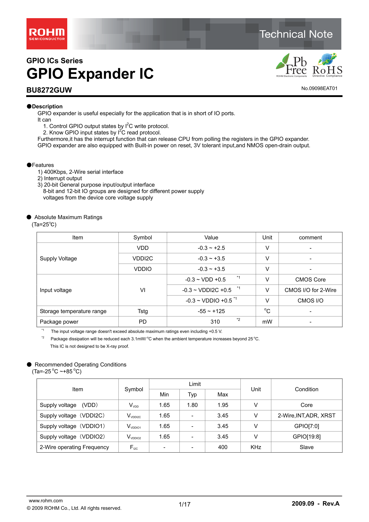
●Description GPIO expander is useful especially for the application that is in short of IO ports. It can 1. Control GPIO output states by I2C write protocol. 2. Know GPIO input states by I2C read protocol. Furthermore,it has the interrupt function that can release CPU from polling the registers in the GPIO expander. GPIO expander are also equipped with Built-in power on reset, 3V tolerant input,and NMOS open-drain output.

●Features 1) 400Kbps, 2-Wire serial interface 2) Interrupt output 3) 20-bit General purpose input/output interface 8-bit and 12-bit IO groups are designed for different power supply voltages from the device core voltage supply

● Absolute Maximum Ratings (Ta=25℃)

Item Symbol Value Unit comment

VDD -0.3 ~ +2.5 V -

Supply Voltage VDDI2C -0.3 ~ +3.5 V -

VDDIO -0.3 ~ +3.5 V -

-0.3 ~ VDD +0.5 *1 V CMOS Core

Input voltage VI -0.3 ~ VDDI2C +0.5 *1 V CMOS I/O for 2-Wire

-0.3 ~ VDDIO +0.5 *1 V CMOS I/O

Storage temperature range Tstg -55 ~ +125 o C - Package power PD 310 *2 m W - *1 The input voltage range doesn't exceed absolute maximum ratings even including +0.5 V. *2 Package dissipation will be reduced each 3.1m W/ o C when the ambient temperature increases beyond 25 o C.

This IC is not designed to be X-ray proof.

● Recommended Operating Conditions (Ta=-25 o C ~+85 o C)

Limit

Item Symbol Unit Condition

Min Typ Max

Supply voltage (VDD) VVDD 1.65 1.80 1.95 V Core Supply voltage(VDDI2C) VVDDI2C 1.65 - 3.45 V 2-Wire,INT,ADR, XRST Supply voltage(VDDIO1) VVDDIO1 1.65 - 3.45 V GPIO[7:0] Supply voltage(VDDIO2) VVDDIO2 1.65 - 3.45 V GPIO[19:8] 2-Wire operating Frequency FI2C - - 400 KHz Slave

www.rohm.com 2009.09 - Rev.A 1/17 © 2009 ROHM Co., Ltd. All rights reserved.

Page Summary Contents For Rohm BU8272GUW Technical Note

Page 1 GPIO ICs Series GPIO Expander IC No.09098EAT01 BU8272GUW ●Description GPIO expander is useful especially for the application that is in short of IO ports. It can 1. Control GPIO output states by I2C w...
Page 2 BU8272GUW Technical Note ● Package Specification(VBGA035W040) Fig.1 Package Specification www.rohm.com 2009.09 - Rev.A 2/17 © 2009 ROHM Co., Ltd. All rights reserved.
Page 3 BU8272GUW Technical Note ● Pin Diagram VDD GPIO1 GPIO3 GPIO5 VDDIO1GPIO0 INT GND GPIO4 GPIO6 GPIO7GPIO2 SCL GND GND GPIO9 GPIO8XRST ADR GND GND GPIO11 GPIO10SDA GPIO17 GPIO15 VDD GPIO12GPIO19 VDDI2C G...
Page 4 BU8272GUW Technical Note ● Block Diagram Functional Block Diagram Interrupt INT INT_MASK Logic VDDI2C IN/OUT Control VDDIO1 8bit GPIO 8bit GPIO[7:0] Input I2C Bus Shift Filter Control SDA Register 12b...
Page 5 BU8272GUW Technical Note ● Electrical Specification VDD=1.8V, VDDIO=3.0V, VDDI2C=3.0V, Ta=25 o C,without output load conditions Limit Item Symbol Unit comment Min. Typ. Max. Input H Voltage VIH 0.75x ...
Page 6 BU8272GUW Technical Note ● Pin-out Functional Descriptions 1. Pin table Power PIN Land Cell PIN name I/O source Function XRST No. number Type system 1 A1 VDDI2C - - 2 (NC) - - - 3 C3 GND - - 4 C1 ADR ...
Page 7 BU8272GUW Technical Note 2. Equivalent IO circuit diagram Fig.4 Equivalent IO circuit diagram www.rohm.com 2009.09 - Rev.A 7/17 © 2009 ROHM Co., Ltd. All rights reserved.
Page 8 BU8272GUW Technical Note ● Functional Description 1 2-Wire Bus Interface 1.1 Slave address Please pull-up SDA and SCL to the same potential of voltage as DVDDI2C. BU8272GUW is controlled by using an o...
Page 9 BU8272GUW Technical Note 1.4 Acknowledge After start condition is occurred, 8 bits data will be transferred. Then the “Master” opens SDA and “Slave” de-asserts SDA to “0” as an “Acknowledge” returned....
Page 10 BU8272GUW Technical Note 1.6 Reading protocol After Writing the slave address and Read/Write commend bits, the next byte is read. The reading register address is next of previous accessed address. The...
Page 11 BU8272GUW Technical Note 1.8 Timing Diagram Transfer (Repeat) Start BIT 7 BIT 6 Ack Stop condition state condition t SU;STA t LOW t HIGH 1/f SCLK t BUF t HD;STA t SU;DAT t HD;DAT t SU;STO Fig. 12 Timi...
Page 12 BU8272GUW Technical Note 2. GPIO・INT Interface The default mode of all GPIO [19:0] ports are input mode upon the power-on. By setting the specific bit of Interrupt Mask Sel register to “1”, the corres...
Page 13 BU8272GUW Technical Note 2.1 Write to GPIO Port After setting the internal register address, the data from master is written from MSB. After Acknowledge is returned, the value of each GPIO port will b...
Page 14 BU8272GUW Technical Note 2.2 Read From GPIO Port After slave address and R/W bit is written, the GPIO ports value will be read into the GPIO registers. (refer to section 8.1.6 for 2-wire reading proto...
Page 15 BU8272GUW Technical Note ● The Setting Registers When setting address is written beyond 00h~09h, the register address will be forced to value 00h. When the final address is set to 09h, then the next a...
Page 16 BU8272GUW Technical Note ● Appendix 1. About difference between I2C and 2-Wire 2-wire interface logic uses a normal IN/OUT cell (Hi-Z or only “0” output) instead of an Open-Drain cell in normal I2C in...
Page 17 BU8272GUW Technical Note ●Ordering part number Part No. Part No. Package Packaging and forming specification GUW: E2: Embossed tape and reel VBGA035W040 VBGA035W040 <Tape and Reel information> 1...
Page 18 Notice No copying or reproduction of this document, in part or in whole, is permitted without the consent of ROHM Co.,Ltd. The content specified herein is subject to change for improvement without not...

Manual Details

Brand ROHM
Pages 18
File Size 398.22 KB
Published July 16, 2026
1 views

Enter the captcha to get the download link:

captcha

Frequently Asked Questions

What is the purpose of this GPIO expander IC?

It expands I/O ports, allowing control and reading of GPIO input states while reducing the need for constant CPU polling via an interrupt function.

Does it have built-in reset functionality or specific power tolerance?

Yes, it includes Built-in power on reset, is 3V tolerant for inputs, and has NMOS open-drain output.

What communication protocols are supported?

It supports a 400Kbps, 2-Wire serial interface (I2C) and handles both general purpose input/output through dedicated buses.

What is the recommended operating temperature range?

The recommended operating condition for this IC is -25°C to +85°C.