# A B C D E F G H I J K L M N O P Q R S T U V W X Y Z

Philips PBSS4140DPN Low-Voltage NPN/PNP Transistor Data Handbook / Specifications Guide

Summary

A highly reliable, compact NPN/PNP low voltage transistor pair designed for general switching and signal control in space-constrained applications. This component minimizes required PCB area while providing high current capability and reduced power dissipation compared to standard discrete packages. The accompanying manual offers complete technical data, detailing absolute maximum ratings, thermal characteristics, load curves, and electrical parameters necessary for robust circuit design. It is ideally suited for miniature electronic equipment, including battery-powered mobile phones, video cameras, LCD backlighting circuits, and general supply line switching systems.
📄 Preview PAGE OF 12

Page 1 Text Content

查询PBSS4140DPN供应商

DISCRETE SEMICONDUCTORS

DATA SHEET

book, halfpage

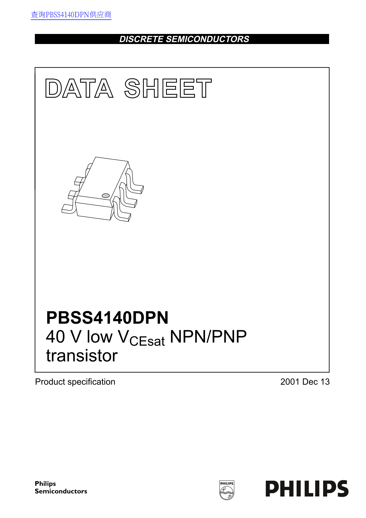
PBSS4140DPN V low VCEsat NPN/PNP transistor Product specification Dec

Page Summary Contents For Philips PBSS4140DPN Low-Voltage NPN/PNP Transistor Data Handbook / Specifications Guide

Page 1 查询PBSS4140DPN供应商 DISCRETE SEMICONDUCTORS DATA SHEET book, halfpage PBSS4140DPN V low VCEsat NPN/PNP transistor Product specification Dec
Page 2 Philips Semiconductors Product specification V low VCEsat NPN/PNP transistor PBSS4140DPN FEATURES QUICK REFERENCE DATA m W total power dissipation SYMBOL PARAMETER MAX. UNIT Low collector-emitter satu...
Page 3 Philips Semiconductors Product specification V low VCEsat NPN/PNP transistor PBSS4140DPN LIMITING VALUES In accordance with the Absolute Maximum Rating System (IEC 60134). SYMBOL PARAMETER CONDITIONS ...
Page 4 Philips Semiconductors Product specification V low VCEsat NPN/PNP transistor PBSS4140DPN CHARACTERISTICS Tamb °C unless otherwise specified. SYMBOL PARAMETER CONDITIONS MIN. TYP. MAX. UNIT Per transis...
Page 5 Philips Semiconductors Product specification V low VCEsat NPN/PNP transistor PBSS4140DPN MLD642 MLD635 handbook, halfpage handbook, halfpage (1) VBE (V) IC (m A) IC (m A) TR1 (NPN); VCE V. TR1 (NPN); ...
Page 6 Philips Semiconductors Product specification V low VCEsat NPN/PNP transistor PBSS4140DPN MLD637 handbook, halfpage f T (MHz) IC (m A) TR1 (NPN); VCE V. Fig.6 Transition frequency as a function of coll...
Page 7 Philips Semiconductors Product specification V low VCEsat NPN/PNP transistor PBSS4140DPN MLD638 MLD639 handbook, halfpage handbook, halfpage VBE (V) IC (m A) IC (m A) TR2 (PNP); VCE −5 V. TR2 (PNP); V...
Page 8 Philips Semiconductors Product specification V low VCEsat NPN/PNP transistor PBSS4140DPN MLD641 handbook, halfpage f T (MHz) IC (m A) TR2 (PNP); VCE -10 V. Fig.11 Transition frequency as a function of...
Page 9 Philips Semiconductors Product specification V low VCEsat NPN/PNP transistor PBSS4140DPN PACKAGE OUTLINE Plastic surface mounted package; 6 leads SOT457 pin 1 index detail X scale DIMENSIONS (mm are t...
Page 10 Philips Semiconductors Product specification V low VCEsat NPN/PNP transistor PBSS4140DPN DATA SHEET STATUS PRODUCT DATA SHEET STATUS(1) DEFINITIONS STATUS(2) Objective data Development This data sheet...
Page 11 Philips Semiconductors Product specification V low VCEsat NPN/PNP transistor PBSS4140DPN NOTES
Page 12 Philips Semiconductors – a worldwide company Contact information For additional information please visit http://www.semiconductors.philips.com. Fax: +31 For sales offices addresses send e-mail to: sal...

Manual Details

Brand Philips
Pages 12
File Size 74.01 KB
Published July 12, 2026
1 views

Enter the captcha to get the download link:

captcha

Frequently Asked Questions

What is the total power dissipation when mounting on a PCB?

The total power dissipation is 600 mW per device, assuming ambient temperature conditions.

How does using the PBSS4140DPN improve board design efficiency?

It reduces required PCB area and minimizes pick-and-place costs by replacing two SOT23 packaged transistors.

What are some typical applications for this NPN/PNP transistor pair?

Common uses include general purpose switching, LCD backlighting circuits, and various supply line switching circuits.

What size mounting pad is recommended for the collector?

A single side copper mounting pad of 1 cm is required when placing the device on a printed circuit board.