PHILIPS BUK104-50L S BUK104-50LP SP Data Manual
Summary
This comprehensive manual details the specifications and robust operational features of the PowerMOS TOPFET transistor (BUK104-50L/S). It provides critical electrical ratings, functional block diagrams, and protection mechanisms, including advanced overload and overvoltage clamping capabilities. Designed for high-power switching in demanding industrial and automotive control systems—such as motors and solenoids—this guide is essential reading for electronics engineers and hardware designers needing reliable, durable power solutions.
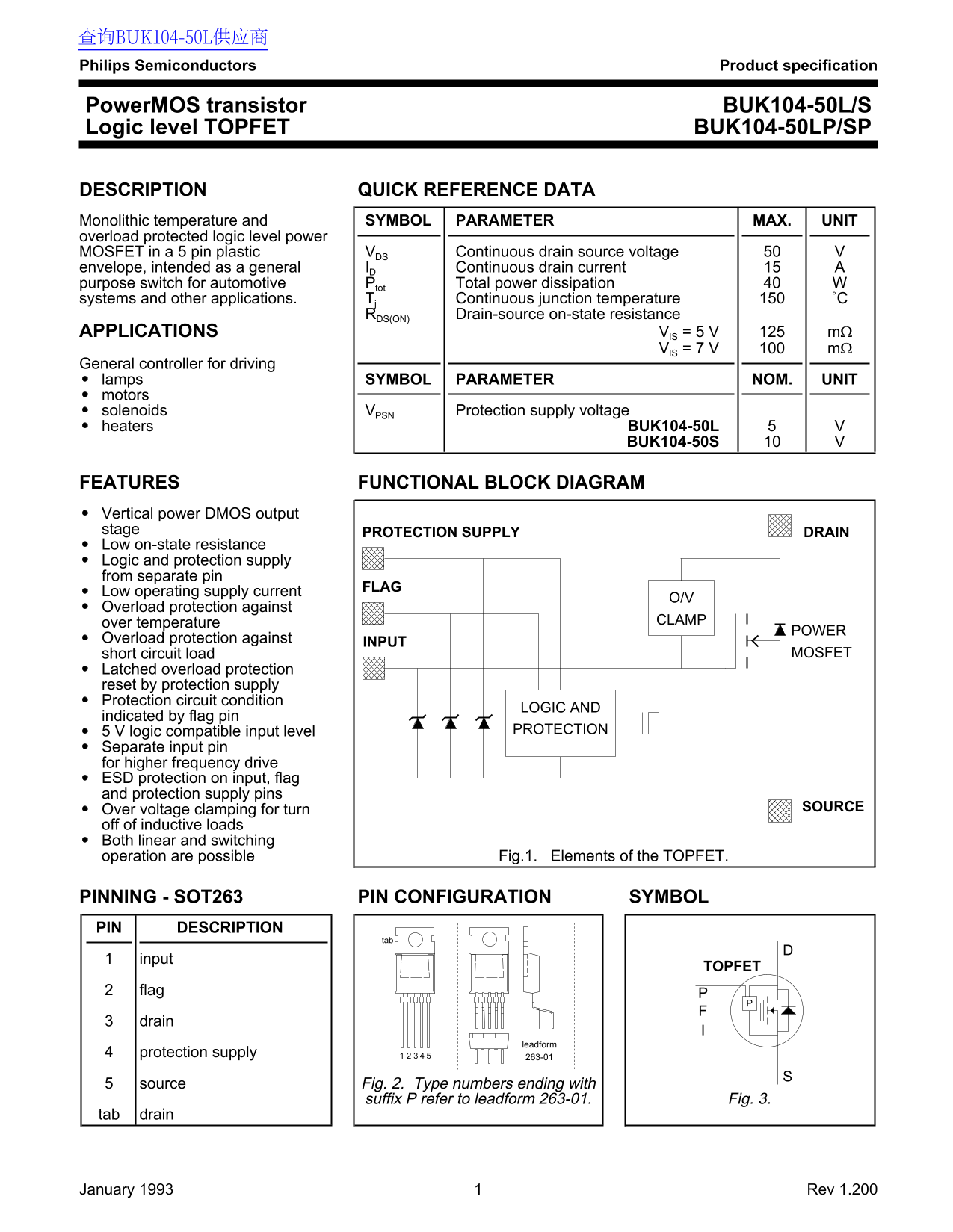
Page 1 Text Content
查询BUK104-50L供应商 Philips Semiconductors Product specification
Power MOS transistor BUK104-50L/S Logic level TOPFET BUK104-50LP/SP
DESCRIPTION QUICK REFERENCE DATA Monolithic temperature and SYMBOL PARAMETER MAX. UNIT overload protected logic level power
MOSFET in a 5 pin plastic VDS Continuous drain source voltage
envelope, intended as a general ID Continuous drain current purpose switch for automotive Ptot Total power dissipation systems and other applications. Tj Continuous junction temperature ˚C
RDS(ON) Drain-source on-state resistance
APPLICATIONS VIS = 5 V mΩ
VIS = 7 V mΩ
General controller for driving lamps SYMBOL PARAMETER NOM. UNIT motors
solenoids VPSN Protection supply voltage
heaters BUK104-50L
BUK104-50S
FEATURES FUNCTIONAL BLOCK DIAGRAM Vertical power DMOS output stage PROTECTION SUPPLY DRAIN Low on-state resistance Logic and protection supply from separate pin
Low operating supply current
Overload protection against
over temperature CLAMP
POWER
Overload protection against
INPUT
short circuit load MOSFET
Latched overload protection reset by protection supply Protection circuit condition
LOGIC AND
indicated by flag pin
5 V logic compatible input level PROTECTION
Separate input pin for higher frequency drive ESD protection on input, flag and protection supply pins
Over voltage clamping for turn SOURCE
off of inductive loads Both linear and switching operation are possible Fig.1. Elements of the TOPFET.
PINNING - SOT263 PIN CONFIGURATION SYMBOL PIN DESCRIPTION
input
TOPFET
flag drain
leadform
protection supply 263-01
source Fig. 2. Type numbers ending with
suffix P refer to leadform 263-01. Fig. 3.
tab drain
January 1993 Rev 1.200
Page Summary Contents For PHILIPS BUK104-50L S BUK104-50LP SP Data Manual
Manual Details
| Brand | Philips |
|---|---|
| Pages | 14 |
| File Size | 151.10 KB |
| Published | July 22, 2026 |
Enter the captcha to get the download link:

Frequently Asked Questions
Can this device be used in life support systems?
No, these products are not designed for use in life support appliances, devices or systems where malfunction could result in personal injury.
What type of overload protection is available for the TOPFET?
The unit supports internal overload protection triggered by high power dissipation and external overload through sensing components.
What should I know about overvoltage transients when using this device?
When operating above 50V, the dedicated power MOSFET actively turns on to clamp overvoltage transients.
Is continuous operation possible if the junction temperature is exceeded?
No, the maximum continuously rated junction temperature (Tj) is 150°C.