Page 1
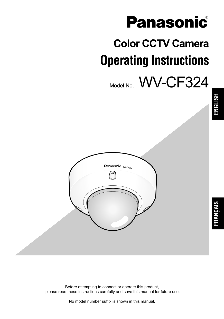
Color CCTV Camera Operating Instructions Model No. WV-CF324 FR AN ÇA IS EN GL IS Before attempting to connect or operate this product, please read these instructions carefully and save this manual for...
Page 2
ENGLISH VERSION WARNING: • This apparatus must be earthed. • To prevent fire or electric shock hazard, do not expose this apparatus to rain or moisture. • The apparatus should not be exposed to drip- ...
Page 3
Important Safety Instructions 1) Read these instructions. 2) Keep these instructions. 3) Heed all warnings. 4) Follow all instructions. 5) Do not use this apparatus near water. 6) Clean only with dry ...
Page 4
Limitation of Liability THIS PUBLICATION IS PROVIDED "AS IS" THIS PUBLICATION COULD INCLUDE WITHOUT WARRANTY OF ANY KIND, TECHNICAL INACCURACIES OR TYPO- EITHER EXPRESS OR IMPLIED, INCLUDING...
Page 5
Preface The WV-CF324 is surveillance color CCTV camera equipped with a 1/4-inch type {1/4"} CCD solid-state image sensor with 768 of horizontal pixels. These cameras can be mounted on a ceiling o...
Page 6
CONTENTS Important Safety Instructions ..................................................................................................... Limitation of Liability ......................................
Page 7
Precautions This product has no power switch. Cleaning the camera body Power is supplied from an external 12 V Turn the power off when cleaning of the cam- DC/24 V AC power-supply device. Refer to era...
Page 8
Use this product for indoor use only. Be sure to remove this product if it is not Do not expose this product to direct sunlight in use. for hours and do not install the product near a heater or an air...
Page 9
Major Operating Controls and Their Functions B. BL D/ AL ON OF EL MONITOR Video output connector B.S. BLC Composite video signals are transmitted. D/N If this unit is connected to the multiplex unit, ...
Page 10
Adaptive Black Stretch selector [B.S.] Focus lever ON: The dark area of the object is auto- matically corrected to lighten it. !0 Zoom lock lever OFF: Does not compensate. Default setting: ON !1 Panni...
Page 11
Installations and Connections Caution: ONLY CONNECT THIS TO 24 V AC OR 12 V DC CLASS 2 POWER SUPPLY. The following installation should be made by qualified service personnel or system installers. Prep...
Page 12
Disassembling the Camera 46mm {1.81"} 1. Remove the top cover. Loosen three fixing screws of the top cover, and remove them. 83.5mm {3.29"} Camera mounting screw x4 (not supplied) To mount t...
Page 13
12 V DC Cable type Extensible length Use the formula below to calculate the power RG-59/U (3C-2V) Approx. 250 m {825 ft} cable and power supply. The voltage sup- plied to the power terminals of the ca...
Page 14
3. Zoom and focus adjustment Panning table Panning At the same time for the pan and tilt adjust- table lock screw ments (Step 2), make zoom and focus adjustments. D/ B. BL AL MONITOR Focus lever AF OF...
Page 15
The AF switch may not adjust the focus Assembling the Camera resulting in LED for AF blinking. For the 1. Mount the top cover. following subjects, select ELC with the Adjust the guide groove of this u...
Page 16
Specifications Power source and power consumption: 24 V AC 60 Hz, 2.7 W 12 V DC, 220 m A Image sensor: 1/4-inch type {1/4"} interline transfer CCD Effective pixels: 768 (H) x 494 (V) Scanning are...
Page 17
Standard Accessories Operating Instructions (this book).................. 1 pc. Warranty card ................................................ 1 pc. Optional Accessories Dome Cover (clear type) .........
Page 18
VERSION FRANÇAISE (FRENCH VERSION) CAUTION ATTENTION RISK OF ELECTRIC SHOCK DO NOT OPEN RISQUE DE CHOCS ELECTRIQUES NE PAS OUVRIR ATTENTION: AFIN DE PRÉVENIR LE RISQUE DE CHOCS ÉLECTRIQUES, NE PAS RET...
Page 19
Instructions de sécurité importantes 1) Veiller à lire ces instructions. 2) Conserver ces instructions. 3) Tenir compte de tous les avertissements. 4) Se conformer à toutes les instructions. 5) Ne pas...
Page 20
Limitation de responsabilité CETTE PUBLICATION EST FOURNIE CETTE PUBLICATION A PU INCLURE DES "COMME TEL" SANS GARANTIE DE TOUTE INEXACTITUDES TECHNIQUES OU DES SORTE, EXPRÈS OU IMPLICITE, É...
Page 21
Préface La caméra vidéo WV-CF3224 est une caméra vidéo CCTV équipée d'un dispositif à couplage de charges à l'état solide CCD de type 1/4 de pouce à résolution de 768 pixels horizontaux. Ces caméras v...
Page 22
TABLE DES MATIÈRES Instructions de sécurité importantes .......................................................................................... Limitation de responsabilité ...........................
Page 23
Mesures de précaution Cet appareil ne possède aucun interrup- Nettoyage du coffret de la caméra vidéo teur d'alimentation. Ne pas oublier de couper l'alimentation avant L‘alimentation est fournie par ...
Page 24
Cet appareil est essentiellement conçu Interférence radio pour un usage sous abri. Si la caméra vidéo est placée près d'un Cet appareil ne doit pas être exposé récepteur de télévision ou d'une antenne...
Page 25
Principaux organes de commande et fonctions B. BL D/ AL ON OF EL MONITOR Connecteur de sortie vidéo B.S. BLC Les signaux vidéo composites sont ALC transmis. Si toutefois l’appareil est connecté à un u...
Page 26
Sélecteur d’extensibilité adaptative du !1 Table de balayage panoramique noir [B.S.] Permet de régler la position du balayage ON: La zone sombre du sujet est auto- panoramique de la caméra vidéo. mati...
Page 27
Installations et connexions Précaution: RACCORDER UNIQUEMENT CET APPAREIL À UNE SOURCE D’ALIMENTATION DE 24 V DE COURANT ALTERNATIF OU DE 12 V DE COURANT CONTINU DE CLASSE 2. L’installation suivante d...
Page 28
Démontage de la caméra vidéo 1. Retirer le couvercle supérieur. 46 mm {1,81"} Desserrer les trois vis de fixation du couvercle supérieur et les retirer. 83,5 mm {3,29"} Vis de fixation de ca...
Page 29
Type de câble Longueur extensible Se servir de la formule indiquée ci-dessous pour calculer la résistance du câble RG-59/U (3C-2V) Environ 250 m {825 ft} d’alimentation et de l’alimentation. La tensio...
Page 30
à –140° (dans le sens inverse des d'azimut de manière à ajuster l’angle aiguilles d'une montre). d’azimut de l’image. (Limites de réglage: Bloquer la vis de blocage de table de ±100°) balayage panoram...
Page 31
Dans ce cas, commander l’ouverture du Assemblage de la caméra diaphragme en dirigeant la caméra vidéo vidéo vers un sujet sombre. Le commutateur AF risque de ne pas 1. Installer le couvercle supérieur...
Page 32
Caractéristiques techniques Source d’alimentation et puissance consommée: 24 V de courant alternatif à 60 Hz, 2,7 W Capteur d'image: Dispositif à transfert de charges interligne CCD de type 1/4 de pou...
Page 33
Accessoires standard Manuel d'utilisation (cette brochure) 1 él. Carte de garantie ............................................... 1 él. Accessoires optionnels Couvercle en dôme (type de transparent) ...
Page 36
Panasonic System Solutions Company, Unit Company of Panasonic Corporation of North America www.panasonic.com/business/ For customer support, call 1.800.528.6747 Three Panasonic Way 2H-2, Secaucus, New...