Page 1
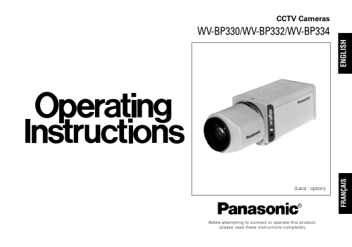
CCTV Cameras WV-BP330/WV-BP332/WV-BP334 (Lens : option) Before attempting to connect or operate this product, please read these instructions completely. FR AN ÇA IS EN GL IS
Page 2
CAUTION RISK OF ELECTRIC SHOCK DO NOT OPEN CAUTION: TO REDUCE THE RISK OF ELECTRIC SHOCK, DO For U.S.A NOT REMOVE COVER (OR BACK). NO USER SER- Warning: VICEABLE PARTS INSIDE. This equipment generates...
Page 3
CONTENTS PREFACE ........................................................................................................................................................................ FEATURES ........
Page 4
PREFACE Panasonic’s WV-BP330 series digital cameras intro- ture elements), and digital signal processing LSI’s. This duce a new level of high picture quality and high reso- model offers cutting-edge t...
Page 5
PRECAUTIONS 1. Do not attempt to disassemble the camera. 5. Clean the CCD faceplate with care. To prevent electric shock, do not remove screws Do not clean the CCD with strong or abrasive or covers. d...
Page 6
MAJOR OPERATING CONTROLS AND THEIR FUNCTIONS <WV-BP330> LL INT OFF AGC ON ELC ALC OFF BLC ON WV-BP330 DC VIDEO Hi-Z G/L 75 VIDEO OUTGEN-LOCK V. PHASE VIDEO LEVEL <WV-BP332> DC 12V IN OFF A...
Page 7
Auto Iris lens Connector AC 24V Input Terminal This connector is for connecting the auto iris lens (AC 24V IN (only WV-BP334)) by a 4-pin male connector supplied as a standard This terminal is for con...
Page 8
!0 Automatic Light Control / Electronic Light DC: Select this mode if you are using the auto iris Control Selector (ALC , ELC) lens that requires a DC drive signal. Lets you select the mode according ...
Page 9
!7 Gen-lock Input Connector (GEN-LOCK) This connector is for connecting an external sys- tem for synchronization. Cautions: 1. Connect to 12V DC (10.5V-16V) or 24V AC (19.5V-28V) class 2 power supply ...
Page 10
CONNECTIONS A. WV-BP330 (120V AC 60Hz) Resistance of copper wire [at 20°C (68°F)] Connect the power cord to an electrical outlet of Copper wire #24 #22 #20 #18 size (AWG) (0.22mm2) (0.33mm2) (0.52mm2)...
Page 11
C. WV-BP334 (24V AC 60Hz) Video Cable Connect the power cable to the AC24V IN terminal 1. It is recommended to use a monitor whose resolu- on the rear panel of the WV-BP334. tion is at least equal to ...
Page 12
Type of RG-59/U RG-6/U RG-11/U RG-15/U coaxial cable (3C-2V) (5C-2V) (7C-2V) (10C-2V) Recommended (m) maximum cable length (ft) 1 650 1 980 2 640 3. Wiring precautions: Do not bend the coaxial cable i...
Page 13
Installation of Auto Iris Lens Connector (2) After connection, assemble the lens connector as follows. Install the lens connector (YFE4191J100) when using a video drive ALC lens. The installation shou...
Page 14
Mounting the Lens Caution for Mounting the Lens Caution: The lens mount should be a C-mount or CS-mount (1”- Before you mount the lens, loosen the two screws 32UN) and the lens weight should be less t...
Page 15
FOCUS OR FLANGE-BACK ADJUSTMENT The following adjustment should be made by qualified 3. Tighten the screws on the flange-back adjusting service personnel or system installers. ring. 1. Loosen the scre...
Page 16
INSTALLATION OF CAMERA Mounting from the bottom Mounting from the top This camera is designed to be mounted from the Remove the mount adapter from the bottom of the bottom, as shown below. The mountin...
Page 17
PREVENTION OF BLOOMING AND SMEAR When the camera is aimed at a bright light, such as a Smear spot light, or a surface that reflects bright light, smear or blooming may appear. Therefore, the camera Br...
Page 18
SPECIFICATIONS Pick-up Device: 768 (H) x 494 (V) pixels, Interline Transfer CCD Scanning Area: 4.9 (H) x 3.7 (V) mm (Equivalent to scanning area of 1/3” pick-up tube) Synchronization: Internal, Extern...
Page 19
Dimensions (without lens): 67 (W) x 55 (H) x 123 (D) mm Weights (without lens): WV-BP330: 0.62kg (1.40lbs) WV-BP332: 0.445kg (0.98lbs) WV-BP334: 0.470kg (1.04lbs) Weights and dimensions indicated are ...
Page 20
VERSION FRANÇAISE Le point d'exclamation dans un triangle (FRENCH VERSION) équilatéral indique que le manuel d'in- structions inclus avec l'appareil contient d'importantes recommandations quant au fon...
Page 21
TABLE DES MATIÈRES PRÉFACE ..................................................................................................................................................................... CARACTÉ...
Page 22
PRÈFACE La caméra vidéo Panasonic de série WV-BP330 intro- cuit à haute intégration de traitement de signaux duit un nouveau niveau technologique de caméra numériques. Ce modèle ouvre définitivement s...
Page 23
MESURES DE PRÉCAUTION 1. Ne jamais essayer de démonter cette caméra 4. Ne jamais se servir de produits détergents ou vidéo de surveillance. abrasifs agressifs pour nettoyer le coffret de la Ne jamais ...
Page 24
7. La caméra vidéo de surveillance ne doit pas être mise en service dans des conditions qui dépassent les limites d’utilisation définies en termes de température, d’humidité ou de puissance d’alimenta...
Page 25
PRINCIPAUX ORGANES DE COMMANDE ET LEURS FONCTIONS <WV-BP330> LL INT OFF AGC ON ELC ALC OFF BLC ON WV-BP330 DC VIDEO Hi-Z G/L 75 VIDEO OUTGEN-LOCK V. PHASE VIDEO LEVEL <WV-BP332> DC 12V IN ...
Page 26
Connecteur de cordon d’objectif à diaphragme Borne d’entrée 24 V de courant alternatif automatique (AC 24V IN (uniquement pour le modèle WV- Ce connecteur est utilisé pour assurer la liaison à BP334))...
Page 27
Sélecteur de mise en service / hors service de BLC ON : La pondération photométrique est contrôle automatique de gain (AGC ON, OFF) accordée au centre de l’écran du moniteur Ce sélecteur est utilisé p...
Page 28
!4 Commande de correction de phase verticale !7 Connecteur d’entrée de verrouilleur de (V.PHASE (uniquement pour les modèles WV- synchronisation (GEN-LOCK) BP330 et WV-BP334) Ce connecteur est utilisé...
Page 29
BRANCHEMENT DE SYSTÈME A. WV-BP330 Procédé de calcul de longueur maximum des câbles à utiliser entre la caméra vidéo de surveil- (courant alternatif 120 V, 60 Hz) lance et la source d’alimentation. Ra...
Page 30
C. WV-BP334 (courant alternati 24 V,60Hz) Câble vidéo Raccorder le cordon d’alimentation à la borne 1. Il est recommandé d’utiliser un moniteur vidéo d’entrée courant alternati 24V IN implantée sur la...
Page 31
Type de RG-59/U RG-6/U RG-11/U RG-15/U Installation d’un connecteur pour câble coaxial (3C-2V) (5C-2V) (7C-2V) (10C-2V) objectif à diaphragme automatique Longueur maxi- (m) Quand un objectif asservi à...
Page 32
(2) Remettre le couvercle du connecteur en place sur Installation de l’objectif le connecteur de la façon suivante dès que le rac- cordement est terminé. Attention: Avant de monter l’objectif sur la c...
Page 33
Mesure de précaution à prendre lors de l’installation de l’objectif La monture d’objectif doit être une monture de type C ou d’une monture de type CS (monture de 1 pouce 32 UN) tandis que le poids de ...
Page 34
RÉGLAGE DE MISE AU POINT OU DE FOYER ARRIÈRE Les réglages mentionnés ci-dessous doivent être Précaution: Si un objectif à monture de type C est exécutés par un technicien professionnel ou des instal- ...
Page 35
INSTALLATION DE LA CAMÉRA VIDÉO DE SURVEILLANCE Fixation par la base de monture sous la partie inférieure de la caméra vidéo de surveillance en procédant de la façon Cette caméra vidéo de surveillance...
Page 36
MESURE PRÉVENTIVE CONTRE L’HYPERLUMINOSITÉ ET LE TRAÎNAGE Lorsque la caméra vidéo de surveillance est dirigée Traînage vers une puissante source d’éclairage telle que des spots d’éclairage ou vers une...
Page 37
CARACTÉRISTIQUES TECHNIQUES Analyseur d'image: Dispositif à transfert de charges interligne avec 768 (H) x 494 (V) pixels Zone de balayage: 4,9 (H) x 3,7 (V) mm (équivalent à lcelle du tube image de 1...
Page 38
Dimensions (sans l’objectif): 67 (L) x 55 (H) x 123 (P) mm [2-5/8 po (L) x 2-3/16 po (H) x 4-13/16 po (P)] Poids (sans l’objectif): WV-BP330: 0,62kg (1,40liv) WV-BP332: 0,445kg (0,98liv) WV-BP334: 0,4...
Page 40
Panasonic Digital Communications & Security Company PANASONIC CANADA INC. Unit of Matsushita Electric Corporation of America 5770 Ambler Drive, Mississauga, Ontario, L4W 2T3 Canada (905)624-5010 S...