# A B C D E F G H I J K L M N O P Q R S T U V W X Y Z

Panasonic AN8027, AN8037 Data Sheet

Summary

These high-efficiency AN8027/AN8037 integrated circuits are designed for stable AC-DC switching power regulation in consumer electronics. Featuring advanced standby modes, input voltage compensation, and comprehensive protection (OVP/OCP), these ICs ensure reliable performance across varied load conditions while adhering to energy conservation laws. Technical documentation provides detailed electrical characteristics, application notes, and robust operational guidelines, making this essential resource for engineers and designers creating devices such as televisions, printers, and facsimile machines.
📄 Preview PAGE OF 29

Page 1 Text Content

查询AN8037 AN8027供应商 Voltage Regulators

AN8027, AN8037 AC-DC switching power supply control IC with standby mode Overview Unit: mm

The AN8027 and AN8037 are ICs developed for self-

excited switching regulator of RCC local resonance con- trol type. These ICs are designed to achieve stability and high efficiency over a wide input voltage range and loads range (light loads to heavy loads), for supporting input levels used worldwide and improved conformance with energy conservation laws.

Features Support improved conformance with energy conserva-

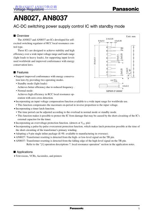
tion laws by providing two operating modes. +0.1 0.3 –0.05

Standby mode (light loads):

Achieves better efficiency due to reduced frequency . Normal mode: SIP009-P-0000C Achieves high efficiency in RCC local resonance op- .3 0. eration with zero-cross detection. Incorporating an input voltage compensation function available to a wide input range for worldwide use. This function compensates the maximum on-period in inverse proportion to the input voltage. Incorporating a timer latch function. The time period can be adjusted according to the overload in normal mode or standby mode. This function makes it possible to protect the IC from damage that may be caused by the short-circuiting of the IC's

external capacitor for the timer.

Incorporating an overvoltage protection function. (detects at VCC pin) Incorporating a pulse-by-pulse overcurrent protection function, which makes latch protection possible at the time of

the short-circuiting of the transformer's primary winding. Adopting a 9-pin single inline package (E-9S: available to manufacturing in overseas). AN8027: Transformer resetting is detected from the high- or low-level signal on the TR pin. AN8037: Transformer resetting is detected from the falling edge of the high-level signal on the TR pin.

Refer to the "[1] operation descriptions 7. local resonance operation" section in the application notes.

Applications Televisions, VCRs, facsimiles, and printers

Page Summary Contents For Panasonic AN8027, AN8037 Data Sheet

Page 1 查询AN8037 AN8027供应商 Voltage Regulators AN8027, AN8037 AC-DC switching power supply control IC with standby mode Overview Unit: mm The AN8027 and AN8037 are ICs developed for self- excited switching reg...
Page 2 AN8027, AN8037 Voltage Regulators Block Diagram INIT(SD latch) Start VREF 7.1 V SD Stop Timer 0.5 V Current reviser (IFB) High-side In OCP In Out clamp Drive I/V VFB CF conv. latch TON High-side Curre...
Page 3 Voltage Regulators AN8027, AN8037 Electrical Characteristics at VCC = 18 V, Ta = 25°C Parameter Symbol Conditions Min Typ Max Unit Low voltage protection (U.V.L.O.) VCC-START 13.4 14.9 16.4 initial st...
Page 4 AN8027, AN8037 Voltage Regulators Electrical Characteristics at VCC = 18 V, Ta = 25°C (continued) Parameter Symbol Conditions Min Typ Max Unit Oscillator (CF) minmum IOFF2-CF IFB = − 0.8 m A −210 −160...
Page 5 Voltage Regulators AN8027, AN8037 Pin Descriptions Pin No. Pin name I/O Explanation Equivalent Circuit TR Transformer reset detection input. When the IC detects transformer resetting and the fall- ing...
Page 6 AN8027, AN8037 Voltage Regulators Pin Descriptions (continued) Pin No. Pin name I/O Explanation Equivalent Circuit Out Output used to directly drive a power MOSFET. A totem pole structure is adopted i...
Page 7 Voltage Regulators AN8027, AN8037 Application Notes [1] Operation descriptions 1. Start/stop circuit block Rectified AC Startup mechanism Startup resistor After the AC voltage is applied and the suppl...
Page 8 AN8027, AN8037 Voltage Regulators Application Notes (continued) [1] Operation descriptions (continued) 2. Oscillation circuit (continued) Setting the on-period (continued) TON : On-period CCF : Value ...
Page 9 Voltage Regulators AN8027, AN8037 Application Notes (continued) [1] Operation descriptions (continued) 2. Oscillation circuit (continued) Setting the off-period The minimum off-period is the charge pe...
Page 10 AN8027, AN8037 Voltage Regulators Application Notes (continued) [1] Operation descriptions (continued) 3. Control waveform timing chart 1) Normal (RCC continuous) operation mode (A)Voltage on bias win...
Page 11 Voltage Regulators AN8027, AN8037 Application Notes (continued) [1] Operation descriptions (continued) 3. Control waveform timing chart (continued) 2) Standby (Intermittent) mode (for light loads) (A)...
Page 12 AN8027, AN8037 Voltage Regulators Application Notes (continued) [1] Operation descriptions (continued) 3. Control waveform timing chart (continued) 3) Pulse-by-pulse overcurrent protection (CLM) opera...
Page 13 Voltage Regulators AN8027, AN8037 Application Notes (continued) [1] Operation descriptions (continued) 4. Power supply output control system (IFB: feedback) Constant-voltage control of the power suppl...
Page 14 AN8027, AN8037 Voltage Regulators Application Notes (continued) [1] Operation descriptions (continued) 5. Soft start (continued) As shown in figure 6, connect R3 and C4 between the Rectified AC FB pin...
Page 15 Voltage Regulators AN8027, AN8037 Application Notes (continued) [1] Operation descriptions (continued) 5. Soft start (continued) Effective period for the soft start The effective period for the soft s...
Page 16 AN8027, AN8037 Voltage Regulators Application Notes (continued) [1] Operation descriptions (continued) 6. Notes on the feedback control (continued) [Countermeasures] If an application exhibits the sym...
Page 17 Voltage Regulators AN8027, AN8037 Application Notes (continued) [1] Operation descriptions (continued) 7. Local resonance operation (power MOSFET turn-on delay circuit) (continued) AN8027, AN8037 VCC ...
Page 18 AN8027, AN8037 Voltage Regulators Application Notes (continued) [1] Operation descriptions (continued) 8. Bottom-on function (AN8037 only) (continued) Select the constants of R9 and C9 to determine th...
Page 19 Voltage Regulators AN8027, AN8037 Application Notes (continued) [1] Operation descriptions (continued) 10. Output block This IC adopts a totem pole (push-pull) structure output circuit in which npn tr...
Page 20 AN8027, AN8037 Voltage Regulators Application Notes (continued) [1] Operation descriptions (continued) 11. Timer latch (continued) Power supply stop Power supply output voltage Power supply IDS stop P...
Page 21 Voltage Regulators AN8027, AN8037 Application Notes (continued) [1] Operation descriptions (continued) 12. Setting the timer period (continued) Timer period (TTIM) is obtained from the following formu...
Page 22 AN8027, AN8037 Voltage Regulators Application Notes (continued) [1] Operation descriptions (continued) 13. Overvoltage protection (OVP) circuit OVP stands for overvoltage protection. The overvoltage p...
Page 23 Voltage Regulators AN8027, AN8037 Application Notes (continued) [1] Operation descriptions (continued) 13. Overvoltage protection (OVP) circuit (continued) Operating supply current characteristics Whe...
Page 24 AN8027, AN8037 Voltage Regulators Application Notes (continued) [1] Operation descriptions (continued) 14. Remote on/off function The SD pin of the AN8027 or AN8037 has a remote on/off function beside...
Page 25 Voltage Regulators AN8027, AN8037 Application Notes (continued) [1] Operation descriptions (continued) 15. Overcurrent protection circuit (pulse-by-pulse overcurrent protection) This circuit uses the ...
Page 26 AN8027, AN8037 Voltage Regulators Application Notes (continued) [1] Operation descriptions (continued) 16. Overcurrent protection circuit (input voltage correction function) (continued) FB voltage FF ...
Page 27 Voltage Regulators AN8027, AN8037 Application Notes (continued) [2] Package power dissipation PD  Ta Independent IC without a heat sink , A Rth j−a = 143°C/W PD = 874 m W (25°C) Po er is si pa tio Am...
Page 28 AN8027, AN8037 Voltage Regulators Application Circuit Examples (continued) Evaluation board chart JP S2 1D pp lic at io oa rd (A dj
Page 29 Request for your special attention and precautions in using the technical information and semiconductors described in this material (1) An export permit needs to be obtained from the competent authori...

Manual Details

Brand Panasonic
Pages 29
File Size 362.86 KB
Published June 16, 2026
1 views

Enter the captcha to get the download link:

captcha

Frequently Asked Questions

What's the difference between AN8027 and AN8037?

AN8027 detects transformer reset from high/low-level TR pin signal; AN8037 detects from falling edge of high-level TR pin.

What voltage triggers the overvoltage protection?

OVP operates at 19.4V to 21.6V supply voltage (Vcc).

What are the operating modes for efficiency?

It offers standby mode for light loads and normal mode for heavy loads to improve efficiency.

What temperature range does this IC require?

Operating ambient temperature: -30°C to +85°C. Storage temperature: -55°C to +150°C.