# A B C D E F G H I J K L M N O P Q R S T U V W X Y Z

Panasonic AN8014S User's Guide and Manual

Summary

Technical datasheet for Panasonic AN8014S single-channel PWM DC-DC converter control IC capable of configuring step-down, step-up, or inverting output types. Features wide operating supply voltage range 3.6V to 34V (limited to 3.6V-17V for step-down configuration), totem pole output circuit with -1A peak current, on-chip pulse-by-pulse overcurrent detection and protection, bootstrap circuit for n-channel MOSFET direct driving, undervoltage lock-out (U.V.L.O.) circuit, on-chip timer latch short-c
📄 Preview PAGE OF 18

Page 1 Text Content

查询AN8014供应商 Voltage regulators

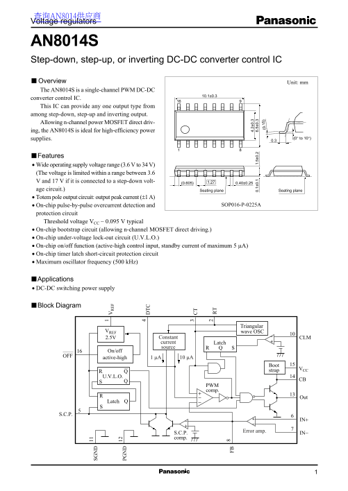
AN8014S Step-down, step-up, or inverting DC-DC converter control IC Overview Unit: mm The AN8014S is a single-channel PWM DC-DC SG 10.1±0.3 converter control IC. This IC can provide any one output type from among step-down, step-up and inverting output. Allowing n-channel power MOSFET direct driv- PG ing, the AN8014S is ideal for high-efficiency power

supplies. (0° to 10°)

■ Features Wide operating supply voltage range (3.6 V to 34 V) (The voltage is limited within a range between 3.6 V and 17 V if it is connected to a step-down volt- 1.27(0.605)

age circuit.) Seating plane Seating plane Totem pole output circuit: output peak current (±1 A)

On-chip pulse-by-pulse overcurrent detection and SOP016-P-0225A

protection circuit Threshold voltage VCC − 0.095 V typical On-chip bootstrap circuit (allowing n-channel MOSFET direct driving.) FB On-chip under-voltage lock-out circuit (U.V.L.O.) On-chip on/off function (active-high control input, standby current of maximum 5 µA)

On-chip timer latch short-circuit protection circuit

Maximum oscillator frequency (500 k Hz) .1 5)

■ Applications DC-DC switching power supply

■ Block Diagram

Triangular

VREF wave OSC

2.5V Constant CLM current Latch source

On/off

active-high 1 µA 10 µA

strap

PWM comp.

Latch

Error amp.

S.C.P. IN− comp.

Page Summary Contents For Panasonic AN8014S User's Guide and Manual

Page 1 查询AN8014供应商 Voltage regulators AN8014S Step-down, step-up, or inverting DC-DC converter control IC Overview Unit: mm The AN8014S is a single-channel PWM DC-DC SG 10.1±0.3 converter control IC. This IC...
Page 2 AN8014S Voltage regulators ■ Pin Descriptions Pin No. Description Pin No. Description Internal reference output Not connected Oscillator timing resistor connection Overcurrent protection input Oscilla...
Page 3 Voltage regulators AN8014S ■ Electrical Characteristics at VCC = 12 V, Ta = 25°C Parameter Symbol Conditions Min Typ Max Unit Reference voltage block Output voltage VREF IREF = −1 m A 2.522 2.6 2.678 ...
Page 4 AN8014S Voltage regulators ■ Electrical Characteristics at VCC = 12 V, Ta = 25°C (continued) Parameter Symbol Conditions Min Typ Max Unit Whole device Total consumption current ICC 5.0 7.0 m A Standby...
Page 5 Voltage regulators AN8014S ■ Terminal Equivalent Circuits Pin No. I / O Equivalent circuit Description VCC VREF: Outputs the reference voltage 2.6 V (allowance: 3%) Incorporating short-circuit protect...
Page 6 AN8014S Voltage regulators ■ Terminal Equivalent Circuits (continued) Pin No. I / O Equivalent circuit Description S.C.P.: Connection for the capacitor that sets the soft start period and the timer la...
Page 7 Voltage regulators AN8014S ■ Terminal Equivalent Circuits (continued) Pin No. I / O Equivalent circuit Description SGND: Signal ground. GND: Output stage ground. Out: Totem pole output. VCC A constant...
Page 8 AN8014S Voltage regulators ■ Application Notes (continued) [1] Function descriptions (continued) 2. The triangular wave generator block (OSC) The triangular wave which swings from approximately 1.32 V...
Page 9 Voltage regulators AN8014S ■ Application Notes (continued) [1] Function descriptions (continued) 4. Timer latch short-circuit protection circuit This circuit protects external main switching devices, ...
Page 10 AN8014S Voltage regulators ■ Application Notes (continued) [1] Function descriptions (continued) 6. Remote circuit It is possible to switch on or off the IC control by using an external control signal...
Page 11 Voltage regulators AN8014S ■ Application Notes (continued) [1] Function descriptions (continued) 8. Overcurrent protection block Utilizing that the overcurrent of power output is proportional to the c...
Page 12 AN8014S Voltage regulators ■ Application Notes (continued) [1] Function descriptions (continued) 9. Bootstrap circuit of output block If the n-channel MOSFET is used as a switching device for DC-DC co...
Page 13 Voltage regulators AN8014S ■ Application Notes (continued) [1] Function descriptions (continued) 9. Bootstrap circuit of output block (continued) 2) N-channel MOSFET (M1) turn-on time: t2 When the PWM...
Page 14 AN8014S Voltage regulators ■ Application Notes (continued) [3] Timing chart OFF pin voltage Low 3.6 V Supply voltage (VCC) Error amplifier output (FB) Internal reference voltage Power supply 1.87 V tu...
Page 15 Voltage regulators AN8014S ■ Application Notes (continued) [3] Timing chart (continued) Output off Turned on in the next cycle. Triangular wave (CT) 1.32 V Error amplifier output (FB) Out pin waveform...
Page 16 AN8014S Voltage regulators sc ill at or re qu en cy k H z) ut pu t d ut ra tio In te rn al ef er en ce ol ta ge ■ Application Notes (continued) [5] Main characteristics Internal reference voltage temp...
Page 17 Voltage regulators AN8014S ■ Application Circuit Examples 1. DC-DC converter control (Example of step-down circuit) In Out 12 V 5 V f = 200 k Hz Triangular wave OSC VREF 2.5V Constant CLM current sour...
Page 18 AN8014S Voltage regulators ■ Application Circuit Examples (continued) 3. DC-DC converter control (Example of polarity-inverting circuit) In Out Triangular wave OSC VREF 2.5V Constant CLM current sourc...

Manual Details

Brand Panasonic
Pages 18
File Size 184.63 KB
Published June 19, 2026
5 views

Enter the captcha to get the download link:

captcha

Frequently Asked Questions

What is the recommended operating temperature range for this IC?

The maximum operating ambient temperature (Topr) is -30 to +85 °C.

Can the AN8014S control step-down, step-up, and inverting power supplies?

Yes, it can provide any one output type from among step-down, step-up, and inverting output.

What is the maximum current capacity of the Totem pole output circuit?

The peak output current for the totem pole circuit is up to 1000 mA (1 A).