# A B C D E F G H I J K L M N O P Q R S T U V W X Y Z

Panasonic AN8013SA User Guide and Manual

Summary

The AN8017SA is a high-efficiency, two-channel PWM DC-DC converter control IC designed for sophisticated low-voltage power applications. This guide provides technical specifics on operating an advanced energy management solution that supports wide supply ranges (1.8V to 14V) and features like U.V.L.O. and precise reference voltage. Ideal for engineers designing compact, portable electronics such as digital cameras, LCD displays, and PDAs requiring reliable, miniaturized power converters.
📄 Preview PAGE OF 25

Page 1 Text Content

查询AN8017SA供应商 Voltage Regulators

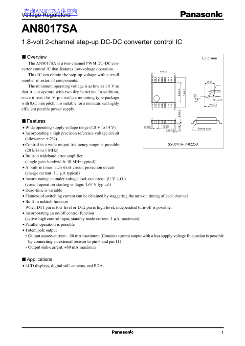
AN8017SA 1.8-volt 2-channel step-up DC-DC converter control IC Overview Unit: mm The AN8017SA is a two-channel PWM DC-DC con- verter control IC that features low-voltage operation.

This IC can obtain the step-up voltage with a small number of external components. (1.0) The minimum operating voltage is as low as 1.8 V so that it can operate with two dry batteries. In addition, since it uses the 16-pin surface mounting type package

0° to 10°

with 0.65 mm pitch, it is suitable for a miniaturized highly 0.5±0.2 efficient potable power supply.

Features

Wide operating supply voltage range (1.8 V to 14 V) Seating plane

Incorporating a high precision reference voltage circuit (allowance: ± 2%)

Control in a wide output frequency range is possible SSOP016-P-0225A

(20 k Hz to 1 MHz) Built-in wideband error amplifier (single gain bandwidth: 10 MHz typical) A built-in timer latch short-circuit protection circuit (charge current: 1.1 µA typical)

Incorporating an under-voltage lock-out circuit (U.V.L.O.) 0. 1± 0. 1. 2± 0. 4. 4± 0.

(circuit operation-starting voltage: 1.67 V typical) 6. 4± 0.

Dead-time is variable

Flatness of switching current can be obtained by staggering the turn-on timing of each channel Built-in unlatch function When DT1 pin is low level or DT2 pin is high level, independent turn-off is possible. Incorporating an on/off control function (active-high control input, standby mode current: 1 µA maximum) Parallel operation is possible Totem pole output Output source-current: −50 m A maximum (Constant current output with a less supply voltage fluctuation is possible by connecting an external resistor to pin 6 and pin 11) Output sink-current: +80 m A maximun

Applications LCD displays, digital still cameras, and PDAs

Page Summary Contents For Panasonic AN8013SA User Guide and Manual

Page 1 查询AN8017SA供应商 Voltage Regulators AN8017SA 1.8-volt 2-channel step-up DC-DC converter control IC Overview Unit: mm The AN8017SA is a two-channel PWM DC-DC con- verter control IC that features low-volta...
Page 2 AN8017SA Voltage Regulators Block Diagram 1.19 V VREF On/off Reference Triangular wave Off VCC control voltage source oscillation VREF RB1 0.2 V PWM1 Error amp.1 Unlatch1 IN−1 Out1 Latch 0.9 V VCC FB2...
Page 3 Voltage Regulators AN8017SA Absolute Maximum Ratings Parameter Symbol Rating Unit Supply voltage VCC Off terminal allowable application voltage VOFF IN−1 terminal allowable application voltage *2 VIN−...
Page 4 AN8017SA Voltage Regulators Electrical Characteristics at VCC = 2.4 V, CREF = 0.1 µF, Ta = 25°C (continued) Parameter Symbol Conditions Min Typ Max Unit Error amplifier 1 block Input threshold voltage...
Page 5 Voltage Regulators AN8017SA Electrical Characteristics at VCC = 2.4 V, CREF = 0.1 µF, Ta = 25 °C (continued) Parameter Symbol Conditions Min Typ Max Unit PWM2 block Output full-off input threshold vol...
Page 6 AN8017SA Voltage Regulators Electrical Characteristics at VCC = 2.4 V, CREF = 0.1 µF, Ta = 25°C (continued) Design reference data (continued) Note) The characteristics listed below are theoretical val...
Page 7 Voltage Regulators AN8017SA Terminal Equivalent Circuits (continued) Pin No. Equivalent circuit Description I/O The output pin for error amplifier 1 block. The source current is −47 µA and the sink cu...
Page 8 AN8017SA Voltage Regulators Terminal Equivalent Circuits (continued) Pin No. Equivalent circuit Description I/O Out2: The pin is push-pull type output terminal. The absolute maximum ratings of output ...
Page 9 Voltage Regulators AN8017SA Terminal Equivalent Circuits (continued) Pin No. Equivalent circuit Description I/O Internal circuit The terminal for on/off control. start/stop High-level input: Normal op...
Page 10 AN8017SA Voltage Regulators Usage Notes (continued) 2. Select an n-channel MOSFET having a low gate SBDVIN threshold value The high-level output voltage of out pin of the AN8017SA is VCC − 1.0 V minim...
Page 11 Voltage Regulators AN8017SA Application Notes [1] PD  Ta curves of SSOP016-P-0225A PD  Ta Glass epoxy board (50 × 50 × t0.8 mm3) Rth(j−a) = 171.8°C/W Po er is si pa tio Independent IC without a heat...
Page 12 AN8017SA Voltage Regulators (m (m (O FF SO (O Application Notes (continued) [2] Main characteristics (continued) ISO(OUT)  RB ISI(OUT)  RB VCC = 2.4 V VCC = 14 V VCC = 14 V VCC = 2.4 V VCC = 7 V VCC...
Page 13 Voltage Regulators AN8017SA Application Notes (continued) [3] Timing chart VCC terminal voltage waveform 1.6 V Output short-circuit S.C.P. terminal voltage waveform OSC DT1 Channel 1 Out1 terminal vol...
Page 14 AN8017SA Voltage Regulators Application Notes (continued) [4] Function descriptions 1. Reference voltage block This block is composed of the band gap circuit, and outputs the temperature compensated 1...
Page 15 Voltage Regulators AN8017SA Application Notes (continued) [4] Function descriptions (continued) 5. Timer latch short-circuit protection circuit This circuit protects the external main switching device...
Page 16 AN8017SA Voltage Regulators Application Notes (continued) [5] About logic of PWM block The logic for channel 1 and channel 2 of this IC is reversed. Thereby an input current flatness is realized. At t...
Page 17 Voltage Regulators AN8017SA Application Notes (continued) [6] Time constant setting method for timer latch short-circuit protection circuit The constructional block diagram of protection latch circuit...
Page 18 AN8017SA Voltage Regulators Application Notes (continued) [7] Parallel synchronous operation of multiple ICs Multiple instances of this IC can be operated in parallel. If the OSC terminals (pin 1) and...
Page 19 Voltage Regulators AN8017SA Application Notes (continued) [7] Parallel synchronous operation of multiple ICs (continued) 2. About the operation of short-circuit protection at parallel synchronous oper...
Page 20 AN8017SA Voltage Regulators Application Notes (continued) [8] Setting of Off-terminal connection resistor The start circuit starts its operation when Q1 is turned on. In an organization in which Q1 tu...
Page 21 Voltage Regulators AN8017SA Application Notes (continued) [9] About sequence operation (continued) Out1 operation Out2 operation Out1: Off at DT1 < 0.2 V Out2: Off at DT2 > 0.9 V Operation when ...
Page 22 AN8017SA Voltage Regulators AC Analysis Result Simulation circuit AC 1.19 V f  VPh f  VPh RO1 = 10 kΩ 1 kΩ RO1 = 10 kΩ CO1 = 0.01 µF CO1 = 1 000 p F f (Hz) f (Hz) f  VBD f  VBD CO1 = 0.01 µF CO1 =...
Page 23 Voltage Regulators AN8017SA ai d B Ph as AC Analysis Result (continued) f  Phase f  Phase RO1 = 0 0.001 µF RO1 = 10 kΩ CO1 = 1 µF CO1 = 0.1 µF f (Hz) f (Hz) ai d B Ph as f  Gain f  Gain RO1 = 0 CO...
Page 24 AN8017SA Voltage Regulators Application Circuit Examples Application circuit example 1 Input S. .P ff R9 C10C11 L2 Output2 IN −1 IN +2 R12 CTLC6 C7 FB AN8017SA ut ut L1 Output1 SBD1 Evaluation board A...
Page 25 Voltage Regulators AN8017SA Application Circuit Examples (continued) Application circuit example 2 (Circuit using the AN8017SA/AN8018SA) Input 1.8 V to 3.2 V Input voltage range: 1.8 V to 3.2 V Oscill...

Manual Details

Brand Panasonic
Pages 25
File Size 258.59 KB
Published June 19, 2026
1 views

Enter the captcha to get the download link:

captcha

Frequently Asked Questions

What is the minimum low voltage it can operate on?

The minimum operating supply voltage is as low as 1.8 V, allowing operation with two dry batteries.

Does this module support parallel operation or external control?

Yes, parallel operation is possible; it also incorporates an active-high on/off control function.

What are its maximum output current capabilities?

The maximum output source current is -50 mA and the maximum output sink current is +80 mA.

Is this IC suitable for space-constrained designs?

Yes, it uses a 16-pin surface mounting type package that is suitable for miniaturized power supplies.