Panasonic 2SC1360, 2SC1360A User's Manual
Summary
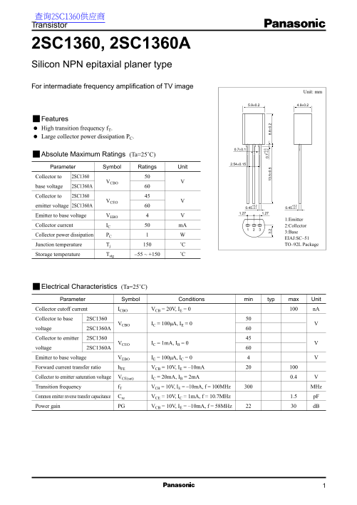
The 2SC1360 and 2SC1360A are silicon NPN epitaxial planar transistors designed for intermediate frequency amplification in TV image circuits. Featuring high transition frequency (300MHz typical), large collector power dissipation (1W), and excellent power gain (22-30dB at 58MHz), they are housed in TO-92L packages. The 2SC1360A variant offers higher voltage ratings (60V vs 50V). Electrical characteristics include low collector-emitter saturation voltage and high current transfer ratio. Target users are analog circuit designers and RF engineers developing television receivers, IF amplifier stages, and general-purpose high-frequency amplification circuits.
Page 1 Text Content
查询2SC1360供应商 Transistor
2SC1360, 2SC1360A Silicon NPN epitaxial planer type For intermadiate frequency amplification of TV image
Unit: mm
Features High transition frequency f T. Large collector power dissipation PC.
Absolute Maximum Ratings (Ta=25˚C)
Parameter Symbol Ratings Unit Collector to 2SC1360
base voltage 2SC1360A
Collector to 2SC1360
emitter voltage 2SC1360A +0.2 +0.2 0.45 –0.1 0.45 –0.1 1.271.27
Emitter to base voltage VEBO
1:Emitter
Collector current IC m A 2:Collector
3:Base
Collector power dissipation PC
EIAJ:SC–51 Junction temperature Tj ˚C TO–92L Package
Storage temperature Tstg –55 ~ +150 ˚C
Electrical Characteristics (Ta=25˚C)
Parameter Symbol Conditions min typ max Unit
Collector cutoff current ICBO VCB = 20V, IE = 0 n A
Collector to base 2SC1360
VCBO IC = 100µA, IE = 0
voltage 2SC1360A
Collector to emitter 2SC1360
VCEO IC = 1m A, IB = 0
voltage 2SC1360A Emitter to base voltage VEBO IE = 100µA, IC = 0 Forward current transfer ratio h FE VCB = 10V, IE = –10m A Collector to emitter saturation voltage VCE(sat) IC = 20m A, IB = 2m A 0.4
Transition frequency f T VCB = 10V, IE = –10m A, f = 100MHz MHz Common emitter reverse transfer capacitance Cre VCE = 10V, IC = 1m A, f = 10.7MHz 1.5 p F
Power gain PG VCB = 10V, IE = –10m A, f = 58MHz d B
Page Summary Contents For Panasonic 2SC1360, 2SC1360A User's Manual
Manual Details
| Brand | Panasonic |
|---|---|
| Pages | 2 |
| File Size | 28.32 KB |
| Published | June 16, 2026 |
Enter the captcha to get the download link:

Frequently Asked Questions
What are the typical applications for the 2SC1360 transistor?
It is designed for intermediate frequency amplification in TV image units.
What is the maximum operating junction temperature for the 2SC1360?
The maximum junction temperature Tj is 150°C.
What is the maximum collector current (Ic) rating for the 2SC1360?
The absolute maximum collector current Ic is 50 mA.
What is the key difference between the 2SC1360 and the 2SC1360A?
The 2SC1360A has higher collector-to-base (VCBO) and collector-to-emitter (VCEO) voltage ratings.
What is the typical transition frequency (fT) for this transistor?
The typical transition frequency fT is 300 MHz under specified test conditions.