Panasonic 2SB0938 2SB0938A Data Sheet
Summary
Enhance your electronic designs with these robust PNP epitaxial planar power transistors. Ideal for high-speed switching and power amplification, this Darlington unit offers a high forward current transfer ratio and direct solder integration for advanced PCB mounting in compact electronics. This comprehensive manual provides engineers with all necessary technical specifications, including absolute maximum ratings, detailed electrical characteristics, thermal handling guidelines, and application best practices to ensure reliable performance in demanding circuit designs.
Page 1 Text Content
Power Transistors
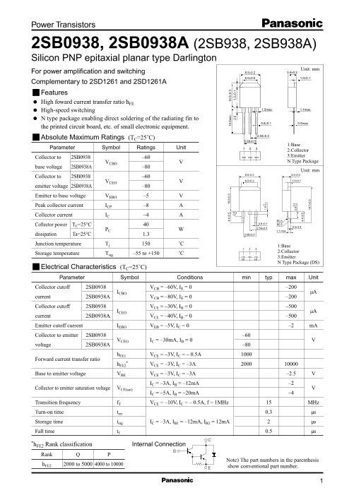
2SB0938, 2SB0938A (2SB938, 2SB938A) Silicon PNP epitaxial planar type Darlington
Unit: mm For power amplification and switching 8.5±0.2 3.4±0.3
Complementary to 2SD1261 and 2SD1261A Features High foward current transfer ratio h FE
High-speed switching 1.5max. 1.1max.
N type package enabling direct soldering of the radiating fin to
0.8±0.1 0.5max.
the printed circuit board, etc. of small electronic equipment.
Absolute Maximum Ratings (TC=25˚C)
1:Base
Parameter Symbol Ratings Unit
2:Collector 3:Emitter
Collector to 2SB0938 –60
VCBO N Type Package
base voltage 2SB0938A –80
Unit: mm 8.5±0.2 3.4±0.3
Collector to 2SB0938 –60
VCEO 6.0±0.3 1.0±0.1
emitter voltage 2SB0938A –80
Emitter to base voltage VEBO –5 Peak collector current ICP –8 Collector current IC –4
Collector power TC=25°C
2.54±0.3 0 to 0.4
PC 4. 4± 0. .0 ±0 .3 .5 in .0 ±0 .3 1.1 max. dissipation Ta=25°C 1.3 5.08±0.5 2. 2. 1. 5± 0.
Junction temperature Tj ˚C
1:Base 2:Collector
Storage temperature Tstg –55 to +150 ˚C
3:Emitter N Type Package (DS) 1. 5+ –0 .4
Electrical Characteristics (TC=25˚C) Parameter Symbol Conditions min typ max Unit Collector cutoff 2SB0938 VCB = –60V, IE = 0 –200
ICBO 0. µA
current 2SB0938A VCB = –80V, IE = 0 –200
Collector cutoff 2SB0938 VCE = –30V, IB = 0 –500
ICEO µA
current 2SB0938A VCE = –40V, IB = 0 –500
Emitter cutoff current IEBO VEB = –5V, IC = 0 –2 m A
Collector to emitter 2SB0938 –60
VCEO IC = –30m A, IB = 0
voltage 2SB0938A –80
h FE1 VCE = –3V, IC = – 0.5A
Forward current transfer ratio
h FE2 VCE = –3V, IC = –3A Base to emitter voltage VBE VCE = –3V, IC = –3A –2.5
IC = –3A, IB = –12m A –2
Collector to emitter saturation voltage VCE(sat)
IC = –5A, IB = –20m A –4
Transition frequency f T VCE = –10V, IC = – 0.5A, f = 1MHz MHz Turn-on time ton 0.3 µs Storage time tstg IC = –3A, IB1 = –12m A, IB2 = 12m A µs Fall time tf 0.5 µs
*h FE2 Rank classification
Internal Connection
Rank h FE2 2000 to 5000 4000 to 10000
Page Summary Contents For Panasonic 2SB0938 2SB0938A Data Sheet
Manual Details
| Brand | Panasonic |
|---|---|
| Pages | 3 |
| File Size | 66.92 KB |
| Published | June 18, 2026 |
Enter the captcha to get the download link:

Frequently Asked Questions
What precautions must be taken regarding component heat dissipation?
Users must comply with guaranteed values, such as using a specified heatsink (e.g., 50 mm x 50 mm) and adhering to maximum ratings.
Can these transistors be used in specialized applications like aerospace or automotive fields?
These products are targeted for general electronics; consult sales staff for information regarding special applications.
What defines the operational limits when designing a circuit?
You must comply with the guaranteed values, particularly the maximum ratings and the specific range of operating power supply voltage and heat dissipation characteristics.