Panasonic 2SA0886 (2SA886) User's Manual
Summary
This datasheet offers complete technical specifications for the 2SA0886 transistor, a high-performance Silicon PNP epitaxial planar type ideal for reliable, low-frequency power amplification circuits. The manual provides engineers with absolute maximum ratings, detailed electrical characteristics (including I-V curves and frequency response), and safe operating thresholds. It serves as a crucial technical resource for electronic designers developing general or specialized equipment that requires dependable transistor performance and robust component selection validation.
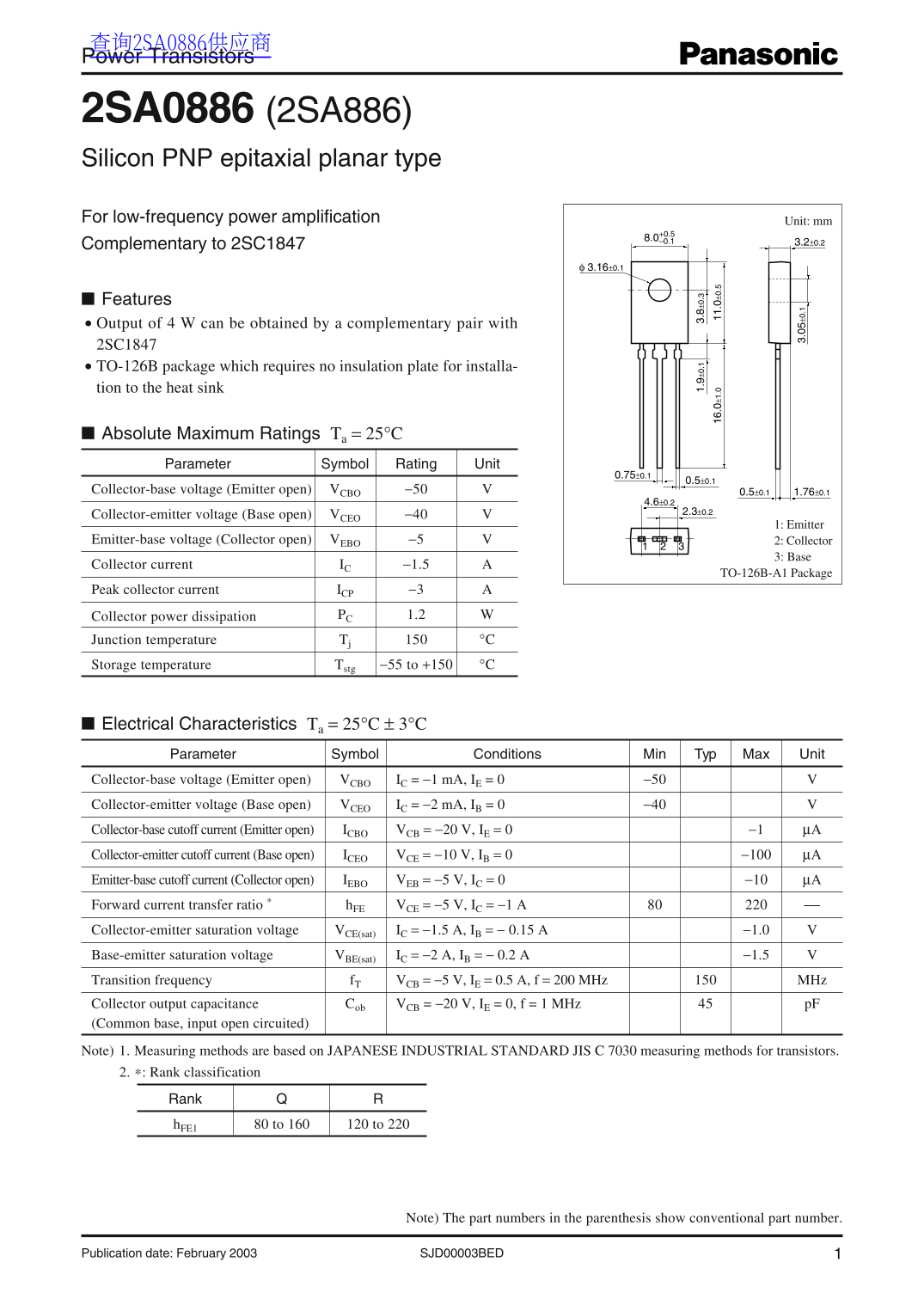
Page 1 Text Content
查询2SA0886供应商 Power Transistors
2SA0886 (2SA886) Silicon PNP epitaxial planar type For low-frequency power amplification Unit: mm
Complementary to 2SC1847 3.2±0.2
Features Output of 4 W can be obtained by a complementary pair with 2SC1847 TO-126B package which requires no insulation plate for installa- tion to the heat sink
Absolute Maximum Ratings Ta = 25°C Parameter Symbol Rating Unit
Collector-base voltage (Emitter open) VCBO −50 0.5±0.1 1.76±0.1
Collector-emitter voltage (Base open) VCEO −40
1: Emitter
Emitter-base voltage (Collector open) VEBO −5 2: Collector
3: Base
Collector current IC −1.5
TO-126B-A1 Package
Peak collector current ICP −3
Collector power dissipation PC 1.2
Junction temperature Tj °C Storage temperature Tstg −55 to +150 °C
Electrical Characteristics Ta = 25°C ± 3°C Parameter Symbol Conditions Min Typ Max Unit Collector-base voltage (Emitter open) VCBO IC = −1 m A, IE = 0 −50
Collector-emitter voltage (Base open) VCEO IC = −2 m A, IB = 0 −40 Collector-base cutoff current (Emitter open) ICBO VCB = −20 V, IE = 0 −1 µA Collector-emitter cutoff current (Base open) ICEO VCE = −10 V, IB = 0 −100 µA Emitter-base cutoff current (Collector open) IEBO VEB = −5 V, IC = 0 −10 µA Forward current transfer ratio * h FE VCE = −5 V, IC = −1 A Collector-emitter saturation voltage VCE(sat) IC = −1.5 A, IB = − 0.15 A −1.0 Base-emitter saturation voltage VBE(sat) IC = −2 A, IB = − 0.2 A −1.5 Transition frequency f T VCB = −5 V, IE = 0.5 A, f = 200 MHz MHz Collector output capacitance Cob VCB = −20 V, IE = 0, f = 1 MHz p F (Common base, input open circuited) Note) 1. Measuring methods are based on JAPANESE INDUSTRIAL STANDARD JIS C 7030 measuring methods for transistors. 2. Rank classification
Rank h FE1 80 to 160 120 to 220
Note) The part numbers in the parenthesis show conventional part number.
SJD00003BED 1Publication date: February 2003
Page Summary Contents For Panasonic 2SA0886 (2SA886) User's Manual
Manual Details
| Brand | Panasonic |
|---|---|
| Pages | 5 |
| File Size | 90.16 KB |
| Published | July 16, 2026 |
Enter the captcha to get the download link:

Frequently Asked Questions
When installing this transistor, are there any special requirements for heat sinks?
It uses a TO-126B package, which requires no separate insulation plate for installation onto the heat sink.
What is the device's maximum absolute voltage rating?
The Collector-base voltage ($V_{CBO}$) and Collector-emitter voltage (Emitter open) are both rated at -50 V.
Is this transistor suitable for mission-critical applications like aerospace or automobiles?
No. Special applications such as those in aircraft, aerospace vehicles, or cars require consulting the sales staff for detailed suitability information.
What is the component's typical collector power dissipation?
The datasheet lists the Collector power dissipation ($P_c$) as 1.2 W under standard conditions.