OMRON Safety Laser Scanner OS32C OS32C Safety Laser Scanner Instruction Sheet (Quick Reference Guide)
Summary
Designed for industrial automation, this manual provides comprehensive guidance for installing and maintaining the high-performance OS32C Laser Safety Scanner. This safety-critical system creates virtual protective fields, greatly enhancing machine guarding capabilities and operational safety compliance. It is essential reading for engineers and technicians responsible for commissioning, tuning, or repairing automated machinery. The guide details setup procedures, safe handling of contaminants (like smoke or dust), network configuration, and optimal deployment strategies to ensure reliable performance in demanding industrial environments.
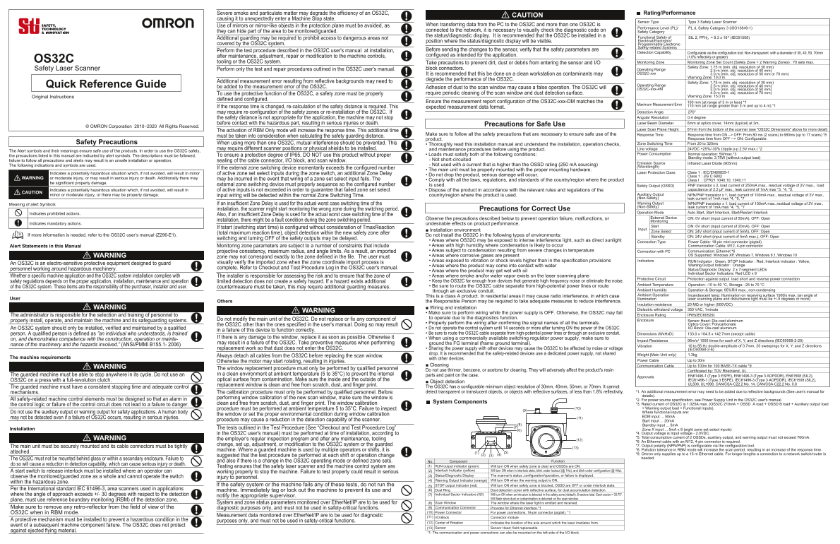
Page 1 Text Content
Severe smoke and particulate matter may degrade the efficiency of an OS32C, Rating/Performance
CAUTION
causing it to unexpectedly enter a Machine Stop state.
Sensor Type Type 3 Safety Laser Scanner
Use of mirrors or mirror-like objects in the protection plane must be avoided, as When transferring data from the PC to the OS32C and more than one OS32C is
Performance Level (PL)/ PL d, Safety Category 3 (ISO13849-1)
they can hide part of the area to be monitored/guarded. connected to the network, it is necessary to visually check the diagnostic code on Safety Category the status/diagnostic display. It is recommended that the OS32C be installed in a
Additional guarding may be required to prohibit access to dangerous areas not Functional Safety of SIL 2, PFHD = 8.3 x 10⁻⁸ (IEC61508) position where the status/diagnostic display will be visible. Electrical/Electronic/
covered by the OS32C system. Programmable Electronic
Safety-related Systems
Perform the test procedure described in the OS32C user's manual at installation, Before sending the changes to the sensor, verify that the safety parameters are
Detection Capability Configurable via the configuration tool; Non-transparent with a diameter of 30, 40, 50, 70mm
after maintenance, adjustment, repair or modification to the machine controls, configured as intended for the application.
(1.8% reflectivity or greater)
OS32C tooling or the OS32C system. Monitoring Zone Monitoring Zone Set Count (Safety Zone + 2 Warning Zones) : 70 sets max.
Take precautions to prevent dirt, dust or debris from entering the sensor and I/O
Safety Zone: 1.75 m (min. obj. resolution of 30 mm)
Safety Laser Scanner Perform only the test and repair procedures outlined in the OS32C user's manual. block connectors. Operating Range
2.5 m (min. obj. resolution of 40 mm)
It is recommended that this be done on a clean workstation as contaminants may OS32C-xxx 3.0 m (min. obj. resolution of 50 mm or 70 mm)
Warning Zone: 10.0 m
degrade the performance of the OS32C.
Additional measurement error resulting from reflective backgrounds may need to Safety Zone: 1.75 m (min. obj. resolution of 30 mm)
Quick Reference Guide Operating Range 2.5 m (min. obj. resolution of 40 mm)
be added to the measurement error of the OS32C. Adhesion of dust to the scan window may cause a false operation. The OS32C will
OS32C-xxx-4M 3.0 m (min. obj. resolution of 50 mm)
To use the protective function of the OS32C, a safety zone must be properly require periodic cleaning of the scan window and dust detection surface. 4.0 m (min. obj. resolution of 70 mm)
Original Instructions Warning Zone: 15.0 m
defined and configured.
Ensure the measurement report configuration of the OS32C-xxx-DM matches the 100 mm (at range of 3 m or less) *1
If the response time is changed, re-calculation of the safety distance is required. This 110 mm (at range greater than 3 m and up to 4 m) *1Maximum Measurement Error
expected measurement data format.
may require re-configuration of the safety zones or re-installation of the OS32C. If Detection Angle 270° the safety distance is not appropriate for the application, the machine may not stop Angular Resolution 0.4 degree before contact with the hazardous part, resulting in serious injuries or death. Laser Beam Diameter 6mm at optics cover, 14mm (typical) at 3m.
Precautions for Safe Use
© OMRON Corporation 2010−2020 All Rights Reserved.
Laser Scan Plane Height 67mm from the bottom of the scanner (see "OS32C Dimensions" above for more detail)
The activation of RBM Only mode will increase the response time. This additional time
Make sure to follow all the safety precautions that are necessary to ensure safe use of the Response Time Response time from ON --> OFF: From 80 ms (2 scans) to 680ms (up to 17 scans) *8
must be taken into consideration when calculating the safety guarding distance.
product. Response time from OFF --> ON: Configurable.
Safety Precautions When using more than one OS32C, mutual interference should be prevented. This Zone Switching Time From 20 to 320ms
• Thoroughly read this installation manual and understand the installation, operation checks,
may require different scanner positions or physical shields to be installed. and maintenance procedures before using the product. Line voltage 24VDC +25%/-30% (ripple p-p 2.5V max.) *2
The Alert symbols and their meanings ensure safe use of the products. In order to use the OS32C safely,
• Loads must satisfy both of the following conditions: Power Consumption Normal operation: 5Wmax.*3
the precautions listed in this manual are indicated by alert symbols. The descriptions must be followed, To ensure a protection degree of IP65, DO NOT use this product without proper
Standby mode: 3.75W (without output load)
failure to follow all precautions and alerts may result in an unsafe installation or operation. sealing of the cable connector, I/O block, and scan window. - Not short-circuited
Emission Source Infrared Laser Diode (905nm)
The following indications and symbols are used. - Not used with a current that is higher than the OSSD rating (250 m A sourcing)
(Wavelength)
If the external zone switching device momentarily exceeds the configured number
• The main unit must be properly mounted with the proper mounting hardware.
Indicates a potentially hazardous situation which, if not avoided, will result in minor of active zone set select inputs during the zone switch, an additional Zone Delay Laser Protection Class Class 1 : IEC/EN60825-1
• Do not drop the product, serious damage will occur. Class 1 : JIS C 6802
WARNING or moderate injury, or may result in serious injury or death. Additionally there may may be incurred in the event that wiring of a zone set select input fails. The
• Comply with all the laws, regulations, and standards of the country/region where the product Class I : CFR21 1040.10, 1040.11
be significant property damage.
external zone switching device must properly sequence so the configured number is used. Safety Output (OSSD) PNP transistor x 2, load current of 250m A max., residual voltage of 2V max., load
Indicates a potentially hazardous situation which, if not avoided, will result in of active inputs is not exceeded in order to guarantee that failed zone set select • Dispose of the product in accordance with the relevant rules and regulations of the capacitance of 2.2 μF max., leak current of 1m A max *3, *4, *5.
CAUTION
minor or moderate injury, or there may be property damage. input wiring will be detected within the normal Zone Switching Time. country/region where the product is used. Auxiliary Output NPN/PNP transistor x 1, load current of 100m A max., residual voltage of 2V max., (Non-Safety) leak current of 1m A max *4, *5, *7 Meaning of alert Symbols If an insufficient Zone Delay is used for the actual worst case switching time of the Warning Output NPN/PNP transistor x 1, load current of 100m A max.,residual voltage of 2V max., (Non-Safety) leak current of 1m A max *4, *5, *7
installation, the scanner might start monitoring the wrong zone during the switching period. Precautions for Correct Use
Indicates prohibited actions. Operation Mode Auto Start, Start Interlock, Start/Restart Interlock
Also, if an insufficient Zone Delay is used for the actual worst case switching time of the
Observe the precautions described below to prevent operation failure, malfunctions, or External Device ON: 0V short (input current of 50m A), OFF: Open
installation, there might be a fault condition during the zone switching period. Monitoring
Indicates mandatory actions. undesirable effects on product performance.
Start ON: 0V short (input current of 20m A), OFF: Open
If tstart (switching start time) is configured without consideration of Tmax Reaction
■ Installation environment Input Zone Select ON: 24V short (input current of 5m A), OFF: Open
(total maximum reaction time), object detection within the new safety zone after
If more information is needed, refer to the OS32C user’s manual (Z296-E1). Do not install the OS32C in the following types of environments: Standby ON: 24V short (input current of 5m A max.), OFF: Open
switching and turning OFF of the safety outputs may be delayed.
• Areas where OS32C may be exposed to intense interference light, such as direct sunlight
Connection Type Power Cable: 18-pin mini-connector (pigtail)
Alert Statements in this Manual Monitoring zone parameters are subject to a number of constraints that include • Areas with high humidity where condensation is likely to occur Communication Cable: M12, 4-pin connector projective consistency, maximum radius, and angle limits. As a result, an imported • Areas subject to condensation resulting from severe changes in temperature Connection with PC Communication: Ethernet *6
WARNING • Areas where corrosive gases are present OS Supported: Windows XP, Windows 7, Windows 8.1, Windows 10
zone may not correspond exactly to the zone defined in the file. The user must
• Areas exposed to vibration or shock levels higher than in the specification provisions Indicators RUN Indicator : Green, STOP Indicator : Red, Interlock Indicator : Yellow,
An OS32C is an electro-sensitive protective equipment designed to guard visually verify the imported zone when the zone coordinate import process is
• Areas where the product may come into contact with water Warning Output Indicator : Orange
personnel working around hazardous machinery. complete. Refer to Checkout and Test Procedure Log in the OS32C user's manual.
• Areas where the product may get wet with oil Status/Diagnostic Display: 2 x 7-segment LEDs Individual Sector Indicators: Red LED x 8
Whether a specific machine application and the OS32C system installation complies with The installer is responsible for assessing the risk and to ensure that the zone of • Areas where smoke and/or water vapor exists on the laser scanning plane
Protective Circuit Protection against output load short and reverse power connection
safety regulations depends on the proper application, installation, maintenance and operation limited detection does not create a safety hazard. If a hazard exists additional • Keep the OS32C far enough from devices that generate high frequency noise or eliminate the noise.
Ambient Temperature Operation: -10 to 50 °C, Storage: -25 to 70 °C
of the OS32C system. These items are the responsibility of the purchaser, installer and user. countermeasure must be taken, this may require additional guarding measures. • Be sure to route the OS32C cable separate from high-potential power lines or route
through an exclusive conduit. Ambient Humidity Operation & Storage: 95%RH max., non-condensing This is a class A product. In residential areas it may cause radio interference, in which case Ambient Operation Incandescent lamp: Illumination on receiving surface 1500lx max. (an angle of
User Illumination laser scanning plane and disturbance light must be +/-5 degrees or more)
Others the Responsible Person may be required to take adequate measures to reduce interference.
Insulation resistance 20 MΩ or higher (500VDC)
WARNING ■ Wiring and installation
Dielectric withstand voltage 350 VAC, 1minute
WARNING
• Make sure to perform wiring while the power supply is OFF. Otherwise, the OS32C may fail
The administrator is responsible for the selection and training of personnel to Enclosure Rating IP65(IEC60529)
to operate due to the diagnostics function.
Do not modify the main unit of the OS32C. Do not replace or fix any component of Enclosure Sensor Head: Die-cast aluminum
properly install, operate, and maintain the machine and its safeguarding systems.
• Properly perform the wiring after confirming the signal names of all the terminals. Optics Cover: Polycarbonate
the OS32C other than the ones specified in the user's manual. Doing so may result
An OS32C system should only be installed, verified and maintained by a qualified • Do not operate the control system until 14 seconds or more after turning ON the power of the OS32C. I/O Block: Die-cast aluminum
in a failure of this device to function correctly.
person. A qualified person is defined as ”an individual who understands, is trained • Be sure to route the OS32C cable separate from high-potential power lines or through an exclusive conduit. Dimensions (Wx Hx D) 133.0 x 104.5 x 142.7mm (except cable)
If there is any damage to the window, replace it as soon as possible. Otherwise it • When using a commercially available switching regulator power supply, make sure to
on, and demonstrates competence with the construction, operation or mainte- Impact Resistance 98m/s 1000 times for each of X, Y, and Z directions (IEC60068-2-29)2
may result in a failure of the OS32C. Take preventive measures when performing ground the FG terminal (frame ground terminal).
nance of the machinery and the hazards involved.” (ANSI/PMMI B155.1- 2006) Vibration 10 to 55 Hz double-amplitude of 0.7mm, 20 sweepings for X, Y, and Z directions
replacement work so that dust does not enter the OS32C. • Sharing the power supply with other devices may cause the OS32C to be affected by noise or voltage (IEC60068-2-6) drop. It is recommended that the safety-related devices use a dedicated power supply, not shared Weight (Main Unit only) 1.3kg
Always detach all cables from the OS32C before replacing the scan window.
The machine requirements with other devices.
Otherwise the motor may start rotating, resulting in injuries. Power Cable Up to 30m
■ Cleaning Communication Cable Up to 100m for 100 BASE-TX cable *9
WARNING The window replacement procedure must only be performed by qualified personnel
Do not use thinner, benzene, or acetone for cleaning. They will adversely affect the product's resin Certificated by: TÜV Rheinland, UL
The guarded machine must be able to stop anywhere in its cycle. Do not use an in a clean environment at ambient temperature (5 to 35°C) to prevent the internal parts and paint on the case.
Approvals EN61496-1 (Type 3 ESPE), EN61496-3 (Type 3 AOPDDR), EN61508 (SIL2),
OS32C on a press with a full-revolution clutch. optical surface from contamination. Make sure the inside and the outside of the IEC61496-1 (Type 3 ESPE), IEC61496-3 (Type 3 AOPDDR), IEC61508 (SIL2),
■ Object detection
replacement window is clean and free from scratch, dust, and finger print. UL508, UL1998, CAN/CSA-C22.2 No. 14, CAN/CSA-C22.2 No. 0.8
The guarded machine must have a consistent stopping time and adequate control The OS32C has a configurable minimum object resolution of 30mm, 40mm, 50mm, or 70mm. It cannot
mechanisms. The calibration procedure must only be performed by qualified personnel. Before detect transparent or translucent objects, or objects with reflective surfaces, of less than 1.8% reflectivity. *1. An additional measurement error may need to be added due to reflective backgrounds (See user's manual for details).
performing window calibration of the new scan window, make sure the window is
All safety-related machine control elements must be designed so that an alarm in *2. For power source specification, see Power Supply Unit in the OS32C user's manual.
clean and free from scratch, dust, and finger print. The window calibration System Components
the control logic or failure of the control circuit does not lead to a failure to danger. *3. Rated current of OS32C is 1.025A max. (OS32C 210m A + OSSD A load + OSSD B load + Auxiliary output load procedure must be performed at ambient temperature 5 to 35°C. Failure to inspect (10) + Warning output load + Functional Inputs).
Do not use the auxiliary output or warning output for safety applications. A human body Where functional inputs are:
the window or set the proper environmental condition during window calibration
may not be detected even if a failure of OS32C occurs, resulting in serious injuries. (11) EDM input ... 50m A
procedure may cause a reduction in the detection capability of the scanner. Start input ... 20m A
(8) Standby input ... 5m A The tests outlined in the Test Procedure (See “Checkout and Test Procedure Log” (7)
Installation (6) Zone X input ... 5m A x 8 (eight zone set select inputs)
in the OS32C user's manual) must be performed at time of installation, according to *4. Output voltage is Input voltage - 2.0VDC. WARNING *5. Total consumption current of 2 OSSDs, auxiliary output, and warning output must not exceed 700m A.
the employer’s regular inspection program and after any maintenance, tooling (12)
*6. An Ethernet cable with an M12, 4-pin connector is required.
change, set up, adjustment, or modification to the OS32C system or the guarded *7. Output polarity (NPN/PNP) is configurable via the configuration tool.
The main unit must be securely mounted and its cable connectors must be tightly (13)
machine. Where a guarded machine is used by multiple operators or shifts, it is *8. Pollution tolerance in RBM mode will increase the scan period, resulting in an increase of the response time.
attached. (1) (5)
(2) (4) *9. Omron only supplies up to a 15 m Ethernet cable. For longer lengths a connection to a network switch/router is
suggested that the test procedure be performed at each shift or operation change (3)
The OS32C must not be mounted behind glass or within a secondary enclosure. Failure to needed.
and also if there is a change in the OS32C operating mode or defined zone sets. No. Component Function
do so will cause a reduction in detection capability, which can cause serious injury or death.
Testing ensures that the safety laser scanner and the machine control system are (1) RUN output indicator (green) Will turn ON when safety zone is clear and OSSDs are ON. A start switch to release interlock must be installed where an operator can (2) Interlock Indicator (yellow) Will turn ON when in interlock state, blink under lockout (@ 1Hz), and blink under configuration (@ 4Hz).
working properly to stop the machine. Failure to test properly could result in serious
(3) Status/Diagnostic Display The scanner's status ,configuration/operation, or failure is displayed.
observe the monitored/guarded zone as a whole and cannot operate the switch injury to personnel.
(4) Warning Output Indicator (orange) Will turn ON when the warning output is ON.
within the hazardous zone.
If the safety system or the machine fails any of these tests, do not run the (5) STOP output indicator (red) Will turn ON when safety zone is blocked, OSSD are OFF or under interlock state.
Per the International standard IEC 61496-3, area scanners used in applications (6) Dust Ring Dust detection cover with reflective surface, for dust accumulation detection
machine. Immediately tag or lock out the machine to prevent its use and
where the angle of approach exceeds +/- 30 degrees with respect to the detection (7) Individual Sector Indicators (ISI) Will turn ON when an intrusion is detected in the safety zone (default), 8 sectors total. Each sector = 33.75°.
notify the appropriate supervisor.
Will flash when dust or contamination is detected on the scan window.
plane, must use reference boundary monitoring (RBM) of the detection zone.
System and zone status parameters monitored over Ether Net/IP are to be used for (8) Scan Window The window where the laser light is emitted and received.
Make sure to remove any retro-reflector from the field of view of the diagnostic purposes only, and must not be used in safety-critical functions. (9) Communication Connector Provides for Ethernet interface.*1
OS32C when in RBM mode. (10) Power Connector For power connections, 18-pin connector (pigtail). *1
Measurement data monitored over Ether Net/IP are to be used for diagnostic (11)
I/O Block Connector module
A protective mechanism must be installed to prevent a hazardous condition in the purposes only, and must not be used in safety-critical functions.
(12) Center of Rotation Indicates the location of the axis around which the laser irradiates from.
event of a subsequent machine component failure. The OS32C does not protect
(13) Sensor Sensor Head; field replaceable.
against ejected flying material.
*1: The communication and power connections can also be mounted on the left side of the I/O block.
Page Summary Contents For OMRON Safety Laser Scanner OS32C OS32C Safety Laser Scanner Instruction Sheet (Quick Reference Guide)
Manual Details
| Brand | Laser |
|---|---|
| Pages | 2 |
| File Size | 221.95 KB |
| Published | June 03, 2026 |
Enter the captcha to get the download link:

Frequently Asked Questions
Does the OS32C detect objects through glass or transparent surfaces?
No, mirrors and mirror-like objects must be avoided as they can hide parts of the monitored area.
What precautions should be taken when setting up multiple OS32C units?
To prevent interference, different scanning positions or physical shields may be required. Mutual interference should also be prevented when transferring data.
How is the safety distance calculated after changes to the system?
If the response time changes, a re-calculation of the safety distance is required to ensure safe operation.
What types of surfaces interfere with the OS32C's performance?
Contaminants like dirt, dust, and retro reflectors or strong interfering light sources can degrade performance and cause false operations.