National Semiconductor LP3945/3946 Battery Charge Management System User's Manual and Specifications
Summary
The LP3945/LP3946 is an integrated charge management system designed to safely charge and maintain various batteries, including Li-Ion and Ni-MH. This module eliminates the need for external components by providing complete programmable control over charging profiles, monitoring features, and protection circuits. The manual details its functionality across diverse operating modes (constant current/voltage), includes dedicated pin descriptions, and provides application guidance for designers working on portable electronics like cell phones, PDAs, digital cameras, and USB-powered devices requiring reliable power solutions.
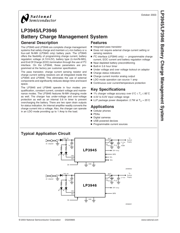
Page 1 Text Content
October
LP 3945/LP attery harge anagem ent ystem
LP3945/LP3946 Battery Charge Management System General Description Features
The LP3945 and LP3946 are complete charge management Integrated pass transistor systems that safely charge and maintain Li-Ion battery or Does not require external charge current setting or four-cell Ni-MH (LP3945 only) battery pack. The LP3945 sensing resistors
offers the flexibility of programming charge current, battery I2C interface (LP3945 only) programmable charge regulation voltage (4.1V/4.2V), battery type (Li-Ion/Ni-MH), current, EOC current and battery regulation voltage and End Of Charge (EOC) termination through the use of I2C
Near-depleted battery preconditioning
interface. On the LP3946, these parameters are pro-
Built-in 5.6 hour timer
grammed at the factory per customer specification.
Under voltage and over voltage lockout on adaptor
The pass transistor, charge current sensing resistor and
Charge status indicators
charge current setting resistors are all integrated inside the
Charge current monitor analog output
LP3945 and LP3946. This eliminates the use of external
LDO mode operation can source amp
components and significantly reduces design time and board
Continuous over current/temperature protection
space. The LP3945 and LP3946 operate in four modes: pre-
Key Specifications
qualification, constant current, constant voltage and mainte-
nance modes. The LP3945 features Ni-MH charging mode 1% charger voltage accuracy over 0˚C TJ 85˚C
as well. The charger has under-voltage and over-voltage 4.5V to 6.0V input voltage range protection as well as an internal 5.6 hr timer to prevent
LLP package power dissipation: 2.7W at TA 25˚C
overcharging the battery. There are two open drain outputs for status indication. An internal amplifier readily converts the
Applications
charge current into voltage. Also, the charger can operate
Cellular phones
in an LDO mode providing up to Amp to the load.
PDAs Digital cameras USB powered devices Programmable current sources
Typical Application Circuit
National Semiconductor Corporation DS200665 www.national.com
Page Summary Contents For National Semiconductor LP3945/3946 Battery Charge Management System User's Manual and Specifications
Manual Details
| Brand | National |
|---|---|
| Pages | 15 |
| File Size | 337.38 KB |
| Published | May 27, 2026 |
Enter the captcha to get the download link:

Frequently Asked Questions
What protection measures prevent battery overcharging?
The system includes under-voltage and over-voltage lockout, along with an internal 5.6 hour timer to prevent accidental overcharging.
Are there required external capacitors for input connections?
Yes. The BATT terminal must have a 10 µF ceramic capacitor to GND, and the CHG-IN pin needs a 1µF ceramic capacitor to GND.
Is it safe to disable the device's safety timer?
No; disabling the timer is not recommended because it bypasses the critical safety function. Users must provide external protection against continuous charging failure.