# A B C D E F G H I J K L M N O P Q R S T U V W X Y Z

NATIONAL SEMICONDUCTOR LP3933 User's Guide

Summary

Boost your portable electronics with this advanced LP3933 Lighting Management System. This highly efficient, programmable DC-DC converter provides comprehensive control for multiple white and RGB LEDs, making it perfect for wireless devices like PDAs or guided lighting displays. The detailed manual serves as a full technical guide, covering all electrical specifications, connection diagrams, operating parameters, and setup instructions needed to achieve precise color mixing, dimming, and flash functions in demanding applications.
📄 Preview 📖 Table of Contents Contents PAGE OF 18

Page 1 Text Content

March

LP Lighting anagem ent ystem for ix hite LE and Tw or FLA LE

LP3933 Lighting Management System for Six White LEDs and Two RGB or FLASH LEDs General Description Features

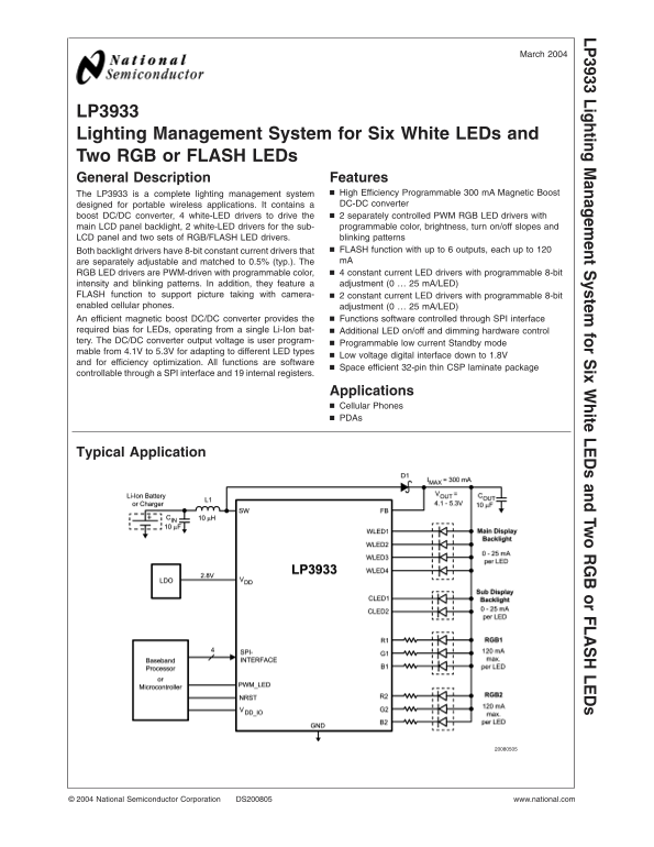
The LP3933 is complete lighting management system High Efficiency Programmable m A Magnetic Boost designed for portable wireless applications. It contains DC-DC converter boost DC/DC converter, white-LED drivers to drive the separately controlled PWM RGB LED drivers with main LCD panel backlight, white-LED drivers for the sub- programmable color, brightness, turn on/off slopes and LCD panel and two sets of RGB/FLASH LED drivers. blinking patterns Both backlight drivers have 8-bit constant current drivers that FLASH function with up to outputs, each up to are separately adjustable and matched to 0.5% (typ.). The m A RGB LED drivers are PWM-driven with programmable color, constant current LED drivers with programmable 8-bit intensity and blinking patterns. In addition, they feature adjustment (0 m A/LED)

FLASH function to support picture taking with camera- constant current LED drivers with programmable 8-bit enabled cellular phones. adjustment (0 m A/LED)

An efficient magnetic boost DC/DC converter provides the Functions software controlled through SPI interface

required bias for LEDs, operating from single Li-Ion bat- Additional LED on/off and dimming hardware control tery. The DC/DC converter output voltage is user program-

Programmable low current Standby mode

mable from 4.1V to 5.3V for adapting to different LED types

Low voltage digital interface down to 1.8V

and for efficiency optimization. All functions are software

Space efficient 32-pin thin CSP laminate package

controllable through SPI interface and internal registers.

Applications Cellular Phones PDAs

Typical Application

National Semiconductor Corporation DS200805 www.national.com

Page Summary Contents For NATIONAL SEMICONDUCTOR LP3933 User's Guide

Page 1 March LP Lighting anagem ent ystem for ix hite LE and Tw or FLA LE LP3933 Lighting Management System for Six White LEDs and Two RGB or FLASH LEDs General Description Features The LP3933 is complete li...
Page 2 Connection Diagrams and Package Mark Information 32-Lead Thin CSP Package, 4.5 5.5 0.8 mm, 0.5 mm pitch LP See NS Package Number SLE32A Package Mark VIEW Note: The actual physical placement of the pac...
Page 3 Pin Description LP Pin Name Type Description FB Input Boost Converter Feedback GND_BOOST Ground Power Switch Ground SW Output Open Drain, Boost Converter Power Switch VDD2 Power Supply Voltage for Int...
Page 4 Absolute Maximum Ratings (Notes 1, ESD Rating (Notes 8, 14) 2) Human Body Model: k V LP Machine Model: 200V If Military/Aerospace specified devices are required, please contact the National Semiconduc...
Page 5 Electrical Characteristics (Notes 2, 11) (Continued) LP Note 9: In applications where high power dissipation and/or poor package thermal resistance is present, the maximum ambient temperature may have...
Page 6 Modes of Operation RESET: In the RESET mode all the internal registers are reset to the default values (Boost output register 3Fh LP (5.0V), all other registers 00h). Reset is entered always if input ...
Page 7 Logic Interface Characteristics LP (1.8V VDD_IO VDD1,2) Symbol Parameter Conditions Min Typ Max Units LOGIC INPUTS SS, SI, SCK, PWM_LED VIL Input Low Level 0.5 VIH Input High Level VDD_IO 0.5 II Logic...
Page 8 SPI Interface (Continued) SPI Timing Diagram SPI Timing Parameters VDD1,2 VDD_IO 2.775V Limit Symbol Parameter Units Min Max Cycle Time ns Enable Lead Time ns Enable Lag Time ns Clock Low Time ns Cloc...
Page 9 Magnetic Boost DC/DC Converter (Continued) LP Boost Converter Topology Magnetic Boost DC/DC Converter Electrical Characteristics Symbol Parameter Conditions Min Typ Max Units ILOAD Load Current 3.0V V...
Page 10 Boost Output Voltage Control User can control the boost output voltage by boost output 8-bit register. LP Boost [7:0] BOOST Output Voltage Boost Output Voltage Control Register 0Dh (typical) Bin Hex 0...
Page 11 Boost Converter Typical Performance Characteristics VIN 3.6V, VOUT 5.0V if not LP otherwise stated. (Continued) Battery Current vs Voltage Battery Current vs Voltage Boost Typical Waveforms at m A Loa...
Page 12 Dual RGB LED Driver The RGB driver has six outputs that can independently drive LP separate RGB LEDs or six LEDs of any kind. User has control over the following parameters separately for each LED: ON...
Page 13 RGB Driver Electrical Characteristics LP (R1, G1, B1, R2, G2, B2 outputs) Symbol Parameter Conditions Min Typ Max Units RDS-ON ON Resistance m A 3.5 ILEAKAGE Off State Leakage Current VFB 5V, LED driv...
Page 14 RGB LED PWM Control (Note 15) (Continued) RSW1 Enable for R1 switch LP GSW1 Enable for G1 switch BSW1 Enable for B1 switch RSW2 Enable for R2 switch GSW2 Enable for G2 switch BSW2 Enable for B2 switch...
Page 15 WLED and CLED Driver Electrical Characteristics LP Symbol Parameter Conditions Min Typ Max Units IRANGE Sink Current Range VFB 5V, Control 00h–FFh 0–25.5 m A IMAX Maximum Sink Current (Note 16) 25.5 m...
Page 16 Recommended External Components (Continued) List of Recommended External Components Symbol Symbol Explanation Value Unit Type CVDD1 VDD1 Bypass Capacitor n F Ceramic, X7R CVDD2 VDD2 Bypass Capacitor n...
Page 17 Control Registers LP Control registers and register bits are shown in the following table. ADDR REGISTER D7 D6 D5 D4 D3 D2 D1 D0 00H RGB Control register1 rgb pwm rgb start rsw1 gsw1 bsw1 rsw2 gsw2 bs...
Page 18 Physical Dimensions inches (millimeters) unless otherwise noted LP Li gh tin an ag em en ys te fo ix hi te LE an Tw or FL LE 32-Lead Thin CSP Package, 4.5 5.5 0.8 mm, 0.5 mm Pitch NS Package Number SL...

Manual Details

Brand National
Pages 18
File Size 406.19 KB
Published June 02, 2026
68 views

Enter the captcha to get the download link:

captcha

Frequently Asked Questions

How are the LED outputs controlled?

The lights are PWM-driven and controlled separately via an SPI interface with programmable color, brightness, and blinking patterns.

What power source can operate this system?

The LP3933 is designed to operate efficiently from a single Li-Ion battery, accommodating 4.1V to 5.3V.

Can the device support camera flash photography?

Yes, it features a dedicated FLASH function with an adjustable current (0...25 mA/LED) for picture taking applications.

What physical interface is used for control?

The system uses a space-efficient 32-pin thin CSP laminate package and is fully controllable through an SPI interface.