# A B C D E F G H I J K L M N O P Q R S T U V W X Y Z

NATIONAL SEMICONDUCTOR LM3150 User's Manual

Summary

The LM3150 SIMPLE SWITCHER Controller is a high-efficiency synchronous step-down power management solution designed for robust power applications ranging from 6V to 42V. This controller offers precise voltage regulation, fast transient response, and comprehensive protection features suitable for critical networking, telecom, and surveillance equipment. The accompanying documentation provides engineers with detailed technical specifications, a deep dive into sophisticated Constant On-Time control architecture, pin descriptions, and application guidance, allowing professional designers to implement reliable, minimum-component power supplies efficiently.
📄 Preview 📖 Table of Contents Contents PAGE OF 20

Page 1 Text Content

IM IT , 4 ro te -D

October 17, 2008

LM3150 SIMPLE SWITCHER® CONTROLLER, 42V Synchronous Step-Down General Description Features The LM3150 SIMPLE SWITCHER® Controller is an easy to Power Wise® step-down controller use and simplified step down power controller capable of pro-

6V to 42V Wide input voltage range

viding up to 12A of output current in a typical application.

Adjustable output voltage down to 0.6V

Operating with an input voltage range of 6V-42V, the LM3150

Programmable switching frequency up to 1 MHz

features an adjustable output voltage down to 0.6V. The

switching frequency is adjustable up to 1 MHz and the syn- No loop compensation required

chronous architecture provides for highly efficient designs. Fully WEBENCH® enabled The LM3150 controller employs a Constant On-Time (COT)

Low external component count

architecture with a proprietary Emulated Ripple Mode (ERM)

Constant On-Time control

control that allows for the use of low ESR output capacitors,

Ultra-fast transient response

which reduces overall solution size and output voltage ripple. The Constant On-Time (COT) regulation architecture allows Stable with low ESR capacitors for fast transient response and requires no loop compensa-

Output voltage pre-bias startup

tion, which reduces external component count and reduces

Valley current limit

design complexity.

Programmable soft-start

Fault protection features such as thermal shutdown, under- voltage lockout, over-voltage protection, short-circuit protec-

Typical Applications

tion, current limit, and output voltage pre-bias startup allow for a reliable and robust solution. Telecom The LM3150 SIMPLE SWITCHER® concept provides for an Networking Equipment easy to use complete design using a minimum number of ex-

Routers

ternal components and National’s WEBENCH® online design

Security Surveillance

tool. WEBENCH® provides design support for every step of

the design process and includes features such as external Power Modules

component calculation with a new MOSFET selector, electri- cal simulation, thermal simulation, and Build-It boards for prototyping.

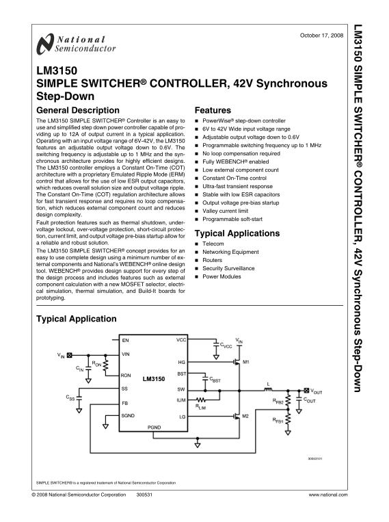
Typical Application

SIMPLE SWITCHER® is a registered trademark of National Semiconductor Corporation

© 2008 National Semiconductor Corporation www.national.com

Page Summary Contents For NATIONAL SEMICONDUCTOR LM3150 User's Manual

Page 1 IM IT , 4 ro te -D October 17, 2008 LM3150 SIMPLE SWITCHER® CONTROLLER, 42V Synchronous Step-Down General Description Features The LM3150 SIMPLE SWITCHER® Controller is an easy to Power Wise® step-dow...
Page 2 Connection Diagram e TSSOP-14 Ordering Information Order Number Package Type NSC Package Drawing Supplied As LM3150MH 94 Units per Anti-Static Tube LM3150MHE e TSSOP-14 MXA14A 250 Units in Tape and Re...
Page 3 All Other Inputs to GND -0.3V to 7V Absolute Maximum Ratings (Note 1) ESD Rating (Note 2) 2 k V If Military/Aerospace specified devices are required, Storage Temperature Range -65°C to +150°C please c...
Page 4 Symbol Parameter Conditions Min Typ Max Units Regulation and Over-Voltage Comparator VFB In-Regulation Feedback Voltage VSS > 0.6V 0.588 0.600 0.612 VFB-OV Feedback Over-Voltage Threshold 0.690 0.7...
Page 5 Simplified Block Diagram www.national.com
Page 6 Typical Performance Characteristics Boost Diode Forward Voltage vs. Temperature ILIM-TH vs. Temperature Quiescent Current vs. Temperature Soft-Start Current vs. Temperature t ON vs. Temperature t ON v...
Page 7 t ON vs. Temperature VCC Current Limit vs. Temperature VCC Dropout vs. Temperature VCC vs. Temperature www.national.com
Page 8 Theory of Operation Programming the Output Voltage The LM3150 synchronous step-down SIMPLE SWITCHER® The output voltage is set by two external resistors Controller utilizes a Constant On-Time (COT) ar...
Page 9 Short-Circuit Protection (8) The LM3150 will sense a short-circuit on the output by mon- itoring the output voltage. When the feedback voltage has Where IOUT is the average output current and ΔIL is t...
Page 10 The soft-start time should be greater than the input voltage Design Guide rise time and also satisfy the following equality to maintain a smooth transition of the output voltage to the programmed The ...
Page 11 FIGURE 2. Inductor Nomograph TABLE 1. Inductor Selection Table Inductor Designator Inductance Current Part Name Vendor L01 7-9 L02 7-9 SER2817H-333KL COILCRAFT L03 7-9 SER2814H-223KL COILCRAFT L04 7-9...
Page 12 Inductor Designator Inductance Current Part Name Vendor L21 1.5 9-12 DR1050-1R5-R COOPER L22 9-12 DO3316H-102 COILCRAFT L23 0.68 9-12 L24 0.47 9-12 L25 12-15 SER2817H-223KL COILCRAFT L26 12-15 L27 12-...
Page 13 5. Determine Output Capacitance Typical hysteretic COT converters similar to the LM3150 re- quire a certain amount of ripple that is generated across the ESR of the output capacitor and fed back to th...
Page 14 high-side FET. It is charged during the SW off-time. The rec- itor, CEN, recommended value is 1000 p F when driving the EN ommended value for CBST is 0.47 µF. The EN bypass capac- pin from open drain ...
Page 15 capacitor should also be able to handle the rms current which Let Cff = 270 p F, which is the closest next standard value. is equal to: 7. MOSFET and RLIM Selection The LM3150 is designed to drive N-c...
Page 16 Pdl = Iout2 x RDS(ON) x (1-D) = 122 x 0.01 x (1-0.275) = 1W 10. CVCC, CEN, and CBST CVCC = 1 µF ceramic with a voltage rating greater than 10V Pdl is also less than the Pdmax specified on the RJK0305D...
Page 17 Bill of Materials Designator Value Parameters Manufacturer Part Number CBST 0.47 µF Ceramic, X7R, 16V, 10% TDK C2012X7R1C474K CBYP 0.1 µF Ceramic, X7R, 50V, 10% TDK C2012X7R1H104K CEN 1000 p F Ceramic...
Page 18 PCB Layout Considerations It is good practice to layout the power components first, such as the input and output capacitors, FETs, and inductor. The first priority is to make the loop between the inpu...
Page 19 Physical Dimensions inches (millimeters) unless otherwise noted 14-Lead e TSSOP Package NS Package Number MXA14A www.national.com
Page 20 IM IT ro te -D Notes For more National Semiconductor product information and proven design tools, visit the following Web sites at: Products Design Support Amplifiers www.national.com/amplifiers WEBEN...

Manual Details

Brand National
Pages 20
File Size 469.15 KB
Published June 04, 2026
46 views

Enter the captcha to get the download link:

captcha

Frequently Asked Questions

What is the input voltage range for the LM3150 controller?

The nominal input voltage range is 6V to 42V.

How do I set the desired output voltage?

Connect a feedback resistor divider between the output and ground at pin FB to set the regulation setting.

Does this device have Over-Voltage Protection (OVP)?

Yes, it provides fault protection features including over-voltage protection, under-voltage lockout, and short-circuit protection.

What is the maximum continuous current capacity?

It features a supply of up to 12A of output current in a typical application.