# A B C D E F G H I J K L M N O P Q R S T U V W X Y Z

NATIONAL SEMICONDUCTOR LM7321 User Guide and Manual

Summary

These high-performance rail-to-rail operational amplifiers are designed for demanding industrial, automotive, and communication applications. Offering a wide voltage range (2.5V to 32V) and robust current capability, they ensure reliable signaling even with capacitive loads or extreme temperature fluctuations (-40°C to 125°C). The provided manual covers comprehensive electrical specifications, including detailed performance metrics like common-mode rejection ratio and output swing, guiding users in integrating these precision components into high-reliability electronic designs.
📄 Preview 📖 Table of Contents Contents PAGE OF 24

Page 1 Text Content

in le / L l R il-to -R il In t/O tp t, ± , H ig tp t C rre t a lim ite itiv ra tio l A lifie

September 5, 2008

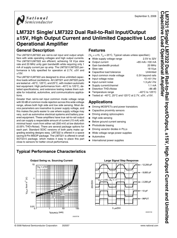
LM7321 Single/ LM7322 Dual Rail-to-Rail Input/Output ±15V, High Output Current and Unlimited Capacitive Load Operational Amplifier General Description Features The LM7321/LM7322 are rail-to-rail input and output ampli- (VS = ±15, TA = 25°C, Typical values unless specified.) fiers with wide operating voltages and high output currents. Wide supply voltage range 2.5V to 32V The LM7321/LM7322 are efficient, achieving 18 V/µs slew

Output current +65 m A/−100 m A

rate and 20 MHz unity gain bandwidth while requiring only 1

Gain bandwidth product 20 MHz

m A of supply current per op amp. The LM7321/LM7322 per-

Slew rate 18 V/µs

formance is fully specified for operation at 2.7V, ±5V and

Capacitive load tolerance Unlimited

Input common mode voltage 0.3V beyond rails

The LM7321/LM7322 are designed to drive unlimited capac-

Input voltage noise 15 n V/√Hz

itive loads without oscillations. All LM7321 and LM7322 parts

Input current noise 1.3 p A/√Hz

are tested at −40°C, 125°C, and 25°C, with modern automatic

Supply current/channel 1.1 m A

test equipment. High performance from −40°C to 125°C, de-

tailed specifications, and extensive testing makes them suit- Distortion THD+Noise −86 d B able for industrial, automotive, and communications applica- Temperature range −40°C to 125°C

tions. Tested at −40°C, 25°C and 125°C at 2.7V, ±5V, ±15V. Greater than rail-to-rail input common mode voltage range with 50 d B of common mode rejection across this wide voltage Applications range, allows both high side and low side sensing. Most de-

Driving MOSFETs and power transistors

vice parameters are insensitive to power supply voltage, and

Capacitive proximity sensors

this makes the parts easier to use where supply voltage may

vary, such as automotive electrical systems and battery pow- Driving analog optocouplers

ered equipment. These amplifiers have true rail-to-rail output High side sensing and can supply a respectable amount of current (15 m A) with

Below ground current sensing

minimal head- room from either rail (300 m V) at low distortion

Photodiode biasing

(0.05% THD+Noise). There are several package options for

each part. Standard SOIC versions of both parts make up- Driving varactor diodes in PLLs

grading existing designs easy. LM7322 is offered in a space Wide voltage range power supplies saving 8-Pin MSOP package. The LM7321 is offered in small

Automotive

SOT23-5 package, which makes it easy to place this part

International power supplies

close to sensors for better circuit performance.

Typical Performance Characteristics

Output Swing vs. Sourcing Current Large Signal Step Response

© 2008 National Semiconductor Corporation www.national.com

Page Summary Contents For NATIONAL SEMICONDUCTOR LM7321 User Guide and Manual

Page 1 in le / L l R il-to -R il In t/O tp t, ± , H ig tp t C rre t a lim ite itiv ra tio l A lifie September 5, 2008 LM7321 Single/ LM7322 Dual Rail-to-Rail Input/Output ±15V, High Output Current and Unlimi...
Page 2 Junction Temperature (Note 4) 150°C Absolute Maximum Ratings (Note 1) Soldering Information: If Military/Aerospace specified devices are required,  Infrared or Convection (20 sec.) 235°C please contac...
Page 3 Symbol Parameter Condition Min Typ Max Units (Note 7) (Note 6) (Note 7) IOUT Output Current Sourcing VID = 200 m V, VOUT = 0V (Note 3) Sinking VID = −200 m V, VOUT = 2.7V (Note 3) IS Supply Current LM...
Page 4 Symbol Parameter Condition Min Typ Max Units (Note 7) (Note 6) (Note 7) VOUT Output Voltage Swing RL = 10 kΩ to 0V High VID = 100 m V RL = 2 kΩ to 0V VID = 100 m V m V from Output Voltage Swing RL = 1...
Page 5 Min Typ Max Symbol Parameter Condition Units (Note 7) (Note 6) (Note 7) AVOL Open Loop Voltage Gain −13V ≤ VO ≤ 13V RL = 10 kΩ to 0V −13V ≤ VO ≤ 13V RL = 2 kΩ to 0V VOUT Output Voltage Swing RL = 10 k...
Page 6 Connection Diagrams 5-Pin SOT-23 8-Pin SOIC 8-Pin MSOP/SOIC Top View Top View Top View Ordering Information Package Part Number Package Media Transport NSC Drawing Marking LM7321MF 1k Units Tape and R...
Page 7 Typical Performance Characteristics Unless otherwise specified: TA = 25°C. Output Swing vs. Sourcing Current Output Swing vs. Sinking Current Output Swing vs. Sourcing Current Output Swing vs. Sinking...
Page 8 VOS Distribution VOS vs. VCM (Unit 1) VOS vs. VCM (Unit 2) VOS vs. VCM (Unit 3) VOS vs. VCM (Unit 1) VOS vs. VCM (Unit 2) www.national.com
Page 9 VOS vs. VCM (Unit 2) VOS vs. VCM (Unit 1) VOS vs. VCM (Unit 2) VOS vs. VCM (Unit 3) VOS vs. VS (Unit 1) VOS vs. VS (Unit 2) www.national.com
Page 10 VOS vs. VS (Unit 3) VOS vs. VS (Unit 1) VOS vs. VS (Unit 2) VOS vs. VS (Unit 3) IBIAS vs. VCM IBIAS vs. VCM www.national.com
Page 11 IBIAS vs. VCM IBIAS vs. VS IBIAS vs. VS IS vs. VCM (LM7321) IS vs. VCM (LM7322) IS vs. VCM (LM7321) www.national.com
Page 12 IS vs. VCM (LM7322) IS vs. VCM (LM7321) IS vs. VCM (LM7322) IS vs. VS (LM7321) IS vs. VS (LM7322) IS vs. VS (LM7321) www.national.com
Page 13 IS vs. VS (LM7322) Positive Output Swing vs. Supply Voltage Positive Output Swing vs. Supply Voltage Negative Output Swing vs. Supply Voltage Negative Output Swing vs. Supply Voltage Open Loop Frequen...
Page 14 Open Loop Frequency Response with Various Resistive Open Loop Frequency Response with Various Supply Load Voltage Phase Margin vs. Capacitive Load CMRR vs. Frequency +PSRR vs. Frequency −PSRR vs. Freq...
Page 15 /L Small Signal Step Response Large Signal Step Response Input Referred Noise Density vs. Frequency Input Referred Noise Density vs. Frequency Input Referred Noise Density vs. Frequency THD+N vs. Freq...
Page 16 THD+N vs. Output Amplitude THD+N vs. Output Amplitude THD+N vs. Output Amplitude Crosstalk Rejection vs. Frequency www.national.com
Page 17 Application Information DRIVING CAPACITIVE LOADS The LM7321/LM7322 are specifically designed to drive un- limited capacitive loads without oscillations as shown in Figure 1. FIGURE 3. −SR vs. Capaciti...
Page 18 FIGURE 6. Buffer Amplifier Scope Photo ESTIMATING THE OUTPUT VOLTAGE SWING FIGURE 4. Output Short Circuit Sourcing Current vs. It is important to keep in mind that the steady state output Input Overdr...
Page 19 FIGURE 10. VCOM Driver Performance Scope Photo FIGURE 8. Output Sinking Characteristics with Load OUTPUT SHORT CIRCUIT CURRENT AND DISSIPATION Lines ISSUES The LM7321/LM7322 output stage is designed f...
Page 20 Table 1 below shows the maximum AC component of the load /L power dissipated by the op amp for standard Sinusoidal, Tri- angular, and Square Waveforms: TABLE 1. Normalized AC Power Dissipated in the O...
Page 21 Physical Dimensions inches (millimeters) unless otherwise noted 5-Pin SOT-23 NS Package Number MF05A 8-Pin MSOP NS Package Number MUA08A www.national.com
Page 22 8-Pin SOIC NS Package Number M08A www.national.com
Page 23 Notes www.national.com
Page 24 in le il -t -R il t/ tp t, ig tp rr li it it iv ra ti li fi Notes For more National Semiconductor product information and proven design tools, visit the following Web sites at: Products Design Support...

Manual Details

Brand National
Pages 24
File Size 746.30 KB
Published June 16, 2026
4 views

Enter the captcha to get the download link:

captcha

Frequently Asked Questions

What is the recommended supply voltage range?

The devices operate with a wide supply voltage range of 2.5V to 32V.

Can these amplifiers handle capacitive loads?

Yes, they are designed to drive unlimited capacitive loads without oscillations.

How do I achieve high performance in extreme temperatures?

They maintain high performance from –40°C to 125°C due to extensive testing and component design.

What makes the LM7321/LM7322 suitable for industrial or automotive uses?

Their robust temperature range (-40°C to 125°C) and wide voltage operating range make them suitable for these demanding applications.