National LMX7300 Data Manual
Summary
The LMP7300 is a micropower precision comparator and reference designed for highly accurate threshold detection in mixed-signal systems. This combined integrated circuit features fine-grain adjustable positive and negative hysteresis control, ultra-low offset voltage, and a stable 2.048V reference source. Ideal for battery monitoring and low-voltage detection applications, it provides reliable performance while minimizing power consumption. The documentation details comprehensive electrical specifications, operating characteristics, and temperature tolerances necessary for engineers designing sophisticated power management systems.
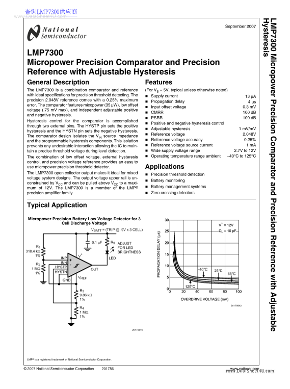
Page 1 Text Content
查询LMP7300供应商 www.Data Sheet4U.com ic ro r P re is io ra to r a re is io fe re ith ju ta le te re is
September 2007
LMP7300 Micropower Precision Comparator and Precision Reference with Adjustable Hysteresis General Description Features The LMP7300 is a combination comparator and reference (For VS = 5V, typical unless otherwise noted) with ideal specifications for precision threshold detecting. The Supply current
precision 2.048V reference comes with a 0.25% maximum
Propagation delay 4 μs
error. The comparator features micopower (35 µW), low offset
Input offset voltage 0.3 m V
voltage (.75 m V max), and independent adjustable positive
CMRR 100 d B
and negative hysteresis.
PSRR 100 d B
Hysteresis control for the comparator is accomplished
Positive and negative hysteresis control
through two external pins. The HYSTP pin sets the positive
Adjustable hysteresis 1 m V/m V
hysteresis and the HYSTN pin sets the negative hysteresis.
Reference voltage 2.048V
The comparator design isolates the VIN source impedance
Reference voltage accuracy 0.25%
and the programmable hysteresis components. This isolation
prevents any undesirable interaction allowing the IC to main- Reference voltage source current 1 m A tain a precise threshold voltage during level detection. Wide supply voltage range 2.7V to 12V The combination of low offset voltage, external hysteresis Operating temperature range ambient −40°C to 125°C
control, and precision voltage reference provides an easy to use micropower precision threshold detector. Applications The LMP7300 open collector output makes it ideal for mixed
Precision threshold detection
voltage system designs. The output voltage upper rail is un-
Battery monitoring
constrained by VCC and can be pulled above VCC to a maxi-
Battery management systems
mum of 12V. The LMP7300 is a member of the LMP®
precision amplifier family. Zero crossing detectors
Typical Application
Micropower Precision Battery Low Voltage Detector for 3
Cell Discharge Voltage
LMP® is a registered trademark of National Semiconductor Corporation.
© 2007 National Semiconductor Corporation www.national.com
Page Summary Contents For National LMX7300 Data Manual
Manual Details
| Brand | National |
|---|---|
| Pages | 14 |
| File Size | 854.40 KB |
| Published | June 06, 2026 |
Enter the captcha to get the download link:
