# A B C D E F G H I J K L M N O P Q R S T U V W X Y Z

National LM1578A LM2578A LM3578A User Manual

Summary

The reliable LM1578A family of switching regulators is an essential component for versatile DC-to-DC voltage conversion circuits, supporting buck, boost, and inverting modes. Operating from 2V to 40V with up to 750 mA output current, it features a unique comparator stage and integrated 1.0V reference, simplifying power management design. This technical manual provides engineers and designers with comprehensive details, including absolute maximum ratings, detailed functional diagrams, electrical specifications, and operational guidelines required for building high-reliability power solutions.
📄 Preview PAGE OF 18

Page 1 Text Content

LM 1578A /LM 2578A /LM 3578A itching egulator

April

LM1578A/LM2578A/LM3578A Switching Regulator General Description Features

The LM1578A is switching regulator which can easily be Inverting and non-inverting feedback inputs

set up for such DC-to-DC voltage conversion circuits as the 1.0V reference at inputs buck, boost, and inverting configurations. The LM1578A fea- Operates from supply voltages of 2V to 40V tures unique comparator input stage which not only has Output current up to m A, saturation less than 0.9V separate pins for both the inverting and non-inverting inputs,

Current limit and thermal shut down

but also provides an internal 1.0V reference to each input,

Duty cycle up to 90%

thereby simplifying circuit design and p.c. board layout. The output can switch up to m A and has output pins for its

collector and emitter to promote design flexibility. An external Applications

current limit terminal may be referenced to either the ground Switching regulators in buck, boost, inverting, and or the Vin terminal, depending upon the application. In addi- single-ended transformer configurations tion, the LM1578A has an on board oscillator, which sets the Motor speed control

switching frequency with single external capacitor from <1

Lamp flasher

Hz to k Hz (typical). The LM1578A is an improved version of the LM1578, offer- ing higher maximum ratings for the total supply voltage and output transistor emitter and collector voltages.

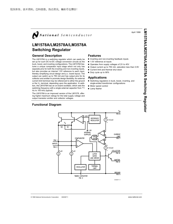
Functional Diagram

DS008711-1

National Semiconductor Corporation DS008711 www.national.com

Page Summary Contents For National LM1578A LM2578A LM3578A User Manual

Page 1 LM 1578A /LM 2578A /LM 3578A itching egulator April LM1578A/LM2578A/LM3578A Switching Regulator General Description Features The LM1578A is switching regulator which can easily be Inverting and non-in...
Page 2 Absolute Maximum Ratings (Note 1) ESD Tolerance (Note 4) k V If Military/Aerospace specified devices are required, please contact the National Semiconductor Sales Office/ Operating Ratings Distributor...
Page 3 Electrical Characteristics (Continued) These specifications apply for 2V VIN 40V (2.2V VIN 40V for TJ −25˚C), timing capacitor CT p F, and 25% duty cycle 75%, unless otherwise specified. Values in sta...
Page 4 Connection Diagram and Ordering Information Metal Can Dual-In-Line Package DS008711-29 Order Number LM3578AM, LM2578AN or LM3578AN See NS Package Number M08A or N08E DS008711-28 Order Number LM1578AH/...
Page 5 Typical Performance Characteristics (Continued) Current Limit Sense Voltage Current Limit Response Time Current Limit Sense Voltage Drift with Temperature for Various Over Drives vs Supply Voltage DS0...
Page 6 Test Circuit* (Continued) DS008711-3 Op amp supplies are ±15V DVM input resistance &gt;100 MΩ *LM1578 max duty cycle is 90% Current Limit Sense Voltage: The voltage at the Current Definition of Terms ...
Page 7 Functional Description (Continued) Applications Information and R2. Thus, both inputs to the comparator will have the po- CURRENT LIMIT tential of the 1.0V reference, VA. When one input, for ex- As me...
Page 8 Applications Information non-inverting input than is sunk by the parallel combination (Continued) of R1 and R2 at the inverting terminal. R3 should be one-fifth of the value of R1 and R2 in parallel. ...
Page 9 Applications Information (Continued) DS008711-30 FIGURE 12. D1 Prevents Output Transistor from DS008711-23 Improperly Turning ON due to D2’s Forward Voltage FIGURE 10. Duty Cycle Adjustment REMOTE SHU...
Page 10 Typical Applications Step 2: Calculate the inductor Volts-sec product, E-Top, ac- (Continued) cording to the equations given from the chart. For the Buck: E-Top (Vin Vo) (Vo/Vin) (1000/fosc) =(15 5) (...
Page 11 Typical Applications (Continued) IG /D In ct an ce al cu la to www.national.com
Page 12 Typical Applications where Vripple is the peak-to-peak output voltage ripple. (Continued) C3 is necessary for continuous operation and is generally in For full line of standard inductor values, contac...
Page 13 Typical Applications R4, C3 and C4 are necessary for continuous operation and (Continued) are typically kΩ, p F, and 0.0022 µF respectively. C1 is the timing capacitor found in Figure 1. C2 Io (Vo Vin...
Page 14 Typical Applications (Continued) DS008711-12 Vin 5V R4 190Ω Vo −15V R5 82Ω Vripple m V R6 kΩ Io m A C1 p F Imin m A C2 µF fosc k Hz C3 p F FIGURE 21. Inverting Regulator BUCK-BOOST REGULATOR RS-232 LI...
Page 15 Typical Applications (Continued) DS008711-14 DS008711-13 Vin 5V R4 0.15Ω 9V Vin 15V R5 ±12V Vo C1 p F Vo 12V C1 p F ±40 Io m A C2 p F Io m A C2 µF fosc k Hz C3 µF Vripple m V C3 p F fosc k Hz C4 0.002...
Page 17 Physical Dimensions inches (millimeters) unless otherwise noted Metal Can Package (H) Order Number LM1578AH/883 or SMD #5962-8958602 NS Package Number H08C Plastic Surface-Mount Package (M) Order Numb...
Page 18 /L /L itc hi ng eg ul at or Physical Dimensions inches (millimeters) unless otherwise noted (Continued) Molded Dual-In-Line Package (N) Order Number LM2578AN or LM3578AN NS Package Number N08ELM LIFE ...

Manual Details

Brand National
Pages 18
File Size 1.10 MB
Published May 27, 2026
90 views

Enter the captcha to get the download link:

captcha

Frequently Asked Questions

What is the operating supply voltage range for the regulator?

The device can operate from a total supply voltage of 2V to 40V.

Can this regulator be used in different topologies?

Yes, it supports buck, boost, and inverting configurations, as well as single-ended transformer applications.

What are the maximum output current and saturation characteristics?

The output can switch up to 750 mA, with a collector saturation voltage of less than 0.9V.

How is the switching frequency determined for motor control?

The on board oscillator sets the switching frequency using a single external capacitor, ranging from Lamp flasher Hz to 100 kHz.