Page 1
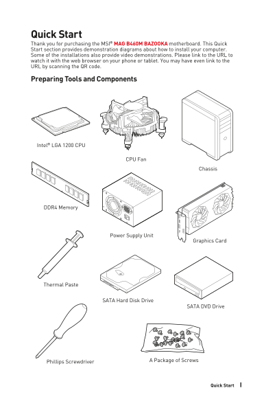
Quick Start Thank you for purchasing the MSI® MAG B460M BAZOOKA motherboard. This Quick Start section provides demonstration diagrams about how to install your computer. Some of the installations also...
Page 2
Safety Information The components included in this package are prone to damage from electrostatic discharge (ESD). Please adhere to the following instructions to ensure successful computer assembly. E...
Page 3
Installing a Processor https://youtu.be/4ce91YC3Oww IIISafety Information
Page 4
Installing DDR4 memory http://youtu.be/T03a Dr JPy Qs DIMMA1 DIMMA2 DIMMA2 DIMMA2 DIMMB2 DIMMB1 DIMMB2 IV Safety Information
Page 5
Connecting the Front Panel Header T S SW http://youtu.be/DPELId VNZUI SE RE WER PO HD D L ED Power LED Power Switch RE SET SW Reserved HDD LED Reset Switch HDD LED + Power LED + HDD LED - Power LED - ...
Page 6
Installing the Motherboard https://youtu.be/w WI6Qt51Wnc Torque: 3 kgf·cm* *3 kgf·cm = 0.3 N·m = 2.6 lbf·in VI Safety Information
Page 7
Connecting the Power Connectors http://youtu.be/gk DYy R_83I4 CPU_PWR1 ATX_PWR1 VIISafety Information
Page 8
Installing SATA Drives http://youtu.be/RZs Mpqxythc VIII Safety Information
Page 9
Installing a Graphics Card http://youtu.be/m G0GZpr9w_A IXSafety Information
Page 10
Connecting Peripheral Devices Safety Information
Page 11
Power On XISafety Information
Page 12
Contents Quick Start ............................................................................................................. Preparing Tools and Components..........................................
Page 13
Onboard LEDs ...................................................................................................... EZ Debug LED ..........................................................................
Page 14
Specifications Supports 10th Gen Intel® Core™ and Pentium® Gold / Celeron® processors for LGA 1200 socket* * Please go to intel.com for compatibility information. * Onboard graphics output are disable...
Page 15
Continued from previous page LAN 1x Realtek® RTL8111H Gigabit LAN Controller Intel® B460 Chipset 6x USB 3.2 Gen 1 5Gbps ports (4 Type-A ports on the USB back panel, 2 ports through the internal USB co...
Page 16
Continued from previous page I/O Controller NUVOTON NCT6687 Controller Chip CPU/System temperature detection Hardware Monitor CPU/System fan speed detection CPU/System fan speed control m ATX Form Fac...
Page 17
Continued from previous page Audio Audio Boost Storage Turbo M.2 Intel® Optane Memory Ready Fan Smart Fan Control LED Mystic Light Special Features Mystic Light Extension (RGB) Mystic Light Extension ...
Page 18
Package contents Please check the contents of your motherboard package. It should contain: Motherboard MAG B460M BAZOOKA User manual Documentation Case stand-off notification Quick installation guide ...
Page 19
Block Diagram 2 Channel DDR4 Memory Processor DMI 3.0 2x PCIe x1 slots 1x SATA 6Gb/s Switch PCH Realtek LAN RTL8111H 3x SATA 6Gb/s 6x USB 2.0 6x USB 3.2 Gen 1 NUVOTON Realtek ALC892/ ALC897 Rear Audio...
Page 20
Rear I/O Panel Line-in PS/2 Combo port Line-out DVI-D USB 3.2 Gen 1 Mic in USB 2.0 Type-A 5Gbps Type A LAN Port LED Status Table Link/ Activity LED Speed LED Status Description Status Description Off ...
Page 21
Device Selection - allows you to select a audio output source to change the related options. The check sign indicates the devices as default. Application Enhancement - the array of options will provid...
Page 22
Overview of Components DIMMB1 DIMMA2 DIMMB2 CPU Socket CPU_PWR1 DIMMA1 CPU_FAN1 PUMP_FAN1 ATX_PWR1 SYS_FAN1 SYS_FAN2 PCI_E1 SATA▼1▲2 JBAT1 PCI_E2 SATA3 PCI_E3 SATA4 JAUD1 JFP1 JRGB1 JTPM1 JRAINBOW1 JC...
Page 23
Component Contents Port Name Port Type Page CPU_FAN1, PUMP_ Fan Connectors FAN1, SYS_FAN1~2 CPU_PWR1, ATX_PWR1 Power Connectors CPU Socket LGA 1200 CPU Socket DIMM Slots Memory slots JAUD1 Front Audio...
Page 24
CPU Socket Distance from the center of the CPU to the nearest DIMM slot. 50.77 mm Introduction to the LGA 1200 CPU The surface of the LGA 1200 CPU has two notches and a golden triangle to assist in co...
Page 25
DIMM Slots DIMMA1 DIMMB1 Channel A Channel B DIMMA2 DIMMB2 Memory module installation recommendation DIMMA1 DIMMA2 DIMMA2 DIMMB1DIMMA2 DIMMB2 DIMMB2 Important Always insert memory modules in the DIMMA...
Page 26
PCI_E1~3: PCIe Expansion Slots PCI_E1: PCIe 3.0 x16 (CPU) PCI_E2: PCIe 3.0 x1 (PCH) PCI_E3: PCIe 3.0 x1 (PCH) Important If you install a large and heavy graphics card, you need to use a tool such as M...
Page 27
M2_1~2: M.2 Slots (Key M) Video Demonstration Watch the video to learn how to Install M.2 module. M2_1 http://youtu.be/JCTFABytr YA Important Intel® RST only supports PCIe M.2 SSD with UEFI ROM. Intel...
Page 28
3. Move the position of the standoffs according to your M.2 SSDs length if need. 4. Insert your M.2 SSD into the M.2 slot at a 30-degree angle. 5. Secure the M.2 SSD in place with the supplied M.2 8.5...
Page 29
JFP1, JFP2: Front Panel Connectors These connectors connect to the switches and LEDs on the front panel. Buzzer 1JFP2 Speaker Speaker - Buzzer + Buzzer - Speaker + Power LED Power Switch Reserved HDD ...
Page 30
CPU_PWR1, ATX_PWR1: Power Connectors These connectors allow you to connect an ATX power supply. CPU_PWR1 Ground +12V Ground +12V Ground +12V Ground +12V Ground Ground +5V PS-ON# Ground Ground +5V Grou...
Page 31
JAUD1: Front Audio Connector This connector allows you to connect audio jacks on the front panel. MIC L Ground MIC R NC Head Phone R MIC Detection SENSE_SEND No Pin Head Phone L Head Phone Detection J...
Page 32
JUSB3: USB 3.2 Gen 1 Connector These connectors allow you to connect USB 3.2 Gen 1 5Gbps ports on the front panel. Power USB2.0+ USB3_RX_DN USB2.0- USB3_RX_DP Ground Ground USB3_TX_C_DP USB3_TX_C_DN U...
Page 33
CPU_FAN1, PUMP_FAN1, SYS_FAN1~2: Fan Connectors Fan connectors can be classified as PWM (Pulse Width Modulation) Mode or DC Mode. PWM Mode fan connectors provide constant 12V output and adjust fan spe...
Page 34
JCI1: Chassis Intrusion Connector This connector allows you to connect the chassis intrusion switch cable. Normal Trigger the chassis (default) intrusion event Using chassis intrusion detector 1. Conn...
Page 35
JBAT1: Clear CMOS (Reset BIOS) Jumper There is CMOS memory onboard that is external powered from a battery located on the motherboard to save system configuration data. If you want to clear the system...
Page 36
JRGB1: RGB LED connector The JRGB connector allows you to connect the 5050 RGB LED strips 12V. RGB LED Strip Connection RGB extension JRGB cable 5050 RGB LED strips 12V connector RGB LED Fan Connectio...
Page 37
JRAINBOW1: Addressable RGB LED connector The JRAINBOW connector allows you to connect the WS2812B Individually Addressable RGB LED strips 5V. JRAINBOW1~2 +5V Data No Pin Ground Addressable RGB LED Str...
Page 38
Onboard LEDs EZ Debug LED These LEDs indicate the debug status of the motherboard. CPU - indicates CPU is not detected or fail. DRAM - indicates DRAM is not detected or fail. VGA - indicates GPU is no...
Page 39
Installing OS, Drivers & Utilities Please download and update the latest utilities and drivers at www.msi.com Installing Windows® 10 1. Power on the computer. 2. Insert the Windows® 10 installatio...
Page 40
UEFI BIOS MSI UEFI BIOS is compatible with UEFI (Unified Extensible Firmware Interface) architecture. UEFI has many new functions and advantages that traditional BIOS cannot achieve, and it will compl...