MAXIM INTEGRATED PRODUCTS MAX1236–MAX1239 2.7V to 3.6V and 4.5V to 5.5V, Low-Power, 4- 12-Channel, 2-Wire Serial, 12-Bit ADCs User Manual
Summary
These ultra-low-power 12-bit Analog-to-Digital Converters (ADCs) provide high-speed, multi-channel data acquisition for demanding applications. Operating efficiently with a single supply from 2.7V to 5.5V, they offer customizable channel configurations (4 or 12 channels) and multiple operating modes, ensuring excellent signal fidelity while consuming minimal power. This manual details the device's advanced features, including internal references and serial interfacing, making it essential for engineers developing portable systems, medical monitors, and remote industrial instrumentation.
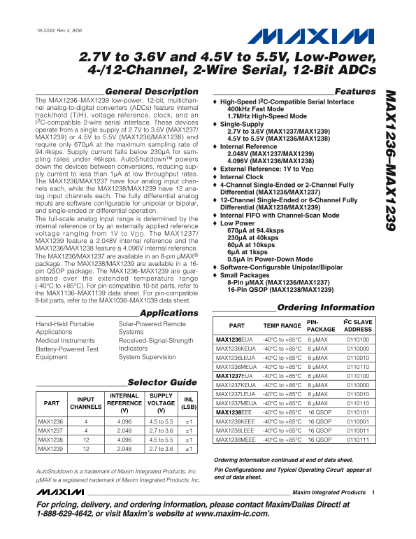
Page 1 Text Content
19-2333; Rev 4; 9/06
2.7V to 3.6V and 4.5V to 5.5V, Low-Power, 4-/12-Channel, 2-Wire Serial, 12-Bit ADCs General Description Features
The MAX1236–MAX1239 low-power, 12-bit, multichan- High-Speed I2C-Compatible Serial Interface nel analog-to-digital converters (ADCs) feature internal 400k Hz Fast Mode track/hold (T/H), voltage reference, clock, and an 1.7MHz High-Speed Mode I2C-compatible 2-wire serial interface. These devices
Single-Supply
operate from a single supply of 2.7V to 3.6V (MAX1237/
2.7V to 3.6V (MAX1237/MAX1239)
MAX1239) or 4.5V to 5.5V (MAX1236/MAX1238) and 4.5V to 5.5V (MAX1236/MAX1238) require only 670µA at the maximum sampling rate of
Internal Reference
94.4ksps. Supply current falls below 230µA for sam-
2.048V (MAX1237/MAX1239)
pling rates under 46ksps. Auto Shutdown™ powers
4.096V (MAX1236/MAX1238)
down the devices between conversions, reducing sup-
External Reference: 1V to VDD
ply current to less than 1µA at low throughput rates.
Internal Clock
The MAX1236/MAX1237 have four analog input chan-
4-Channel Single-Ended or 2-Channel Fully
nels each, while the MAX1238/MAX1239 have 12 ana-
Differential (MAX1236/MAX1237)
log input channels each. The fully differential analog
12-Channel Single-Ended or 6-Channel Fully
inputs are software configurable for unipolar or bipolar,
Differential (MAX1238/MAX1239)
and single-ended or differential operation.
Internal FIFO with Channel-Scan Mode
The full-scale analog input range is determined by the
Low Power
internal reference or by an externally applied reference
670µA at 94.4ksps
voltage ranging from 1V to VDD. The MAX1237/
230µA at 40ksps
MAX1239 feature a 2.048V internal reference and the
60µA at 10ksps
MAX1236/MAX1238 feature a 4.096V internal reference.
6µA at 1ksps
The MAX1236/MAX1237 are available in an 8-pin µMAX®
0.5µA in Power-Down Mode
package. The MAX1238/MAX1239 are available in a 16-
Software-Configurable Unipolar/Bipolar
pin QSOP package. The MAX1236–MAX1239 are guar-
Small Packages
anteed over the extended temperature range
8-Pin µMAX (MAX1236/MAX1237)
(-40°C to +85°C). For pin-compatible 10-bit parts, refer to
16-Pin QSOP (MAX1238/MAX1239)
the MAX1136–MAX1139 data sheet. For pin-compatible 8-bit parts, refer to the MAX1036–MAX1039 data sheet.
Ordering Information
Applications
PIN- I2C SLAVE
Hand-Held Portable Solar-Powered Remote
PART TEMP RANGE
PACKAGE ADDRESS
Applications Systems
Medical Instruments Received-Signal-Strength MAX1236EUA -40°C to +85°C 8 µMAX
Battery-Powered Test Indicators MAX1236KEUA -40°C to +85°C 8 µMAX
Equipment System Supervision MAX1236LEUA -40°C to +85°C 8 µMAX
MAX1236MEUA -40°C to +85°C 8 µMAX MAX1237EUA -40°C to +85°C 8 µMAX
Selector Guide
MAX1237KEUA -40°C to +85°C 8 µMAX MAX1237LEUA -40°C to +85°C 8 µMAX
INTERNAL SUPPLY
INPUT INL
PART REFERENCE VOLTAGE MAX1237MEUA -40°C to +85°C 8 µMAX
CHANNELS (LSB)
MAX1238EEE -40°C to +85°C 16 QSOP MAX1236 4.096 4.5 to 5.5 ±1 MAX1238KEEE -40°C to +85°C 16 QSOP MAX1237 2.048 2.7 to 3.6 ±1 MAX1238LEEE -40°C to +85°C 16 QSOP MAX1238 4.096 4.5 to 5.5 ±1 MAX1238MEEE -40°C to +85°C 16 QSOP
MAX1239 2.048 2.7 to 3.6 ±1
Ordering Information continued at end of data sheet. Pin Configurations and Typical Operating Circuit appear at
Auto Shutdown is a trademark of Maxim Integrated Products, Inc.
end of data sheet.
µMAX is a registered trademark of Maxim Integrated Products, Inc.
Maxim Integrated Products
For pricing, delivery, and ordering information, please contact Maxim/Dallas Direct! at 1-888-629-4642, or visit Maxim’s website at www.maxim-ic.com.
Page Summary Contents For MAXIM INTEGRATED PRODUCTS MAX1236–MAX1239 2.7V to 3.6V and 4.5V to 5.5V, Low-Power, 4- 12-Channel, 2-Wire Serial, 12-Bit ADCs User Manual
Manual Details
| Brand | Maxim Integrated |
|---|---|
| Pages | 22 |
| File Size | 448.51 KB |
| Published | May 26, 2026 |
Enter the captcha to get the download link:

Frequently Asked Questions
What are the supported supply voltage ranges?
The devices operate from 2.7V to 3.6V or 4.5V to 5.5V, depending on the specific model variant.
Can the analog inputs be configured for different signal types?
Yes, the inputs are software configurable for unipolar/bipolar modes and can operate in single-ended or differential configurations.
How does power consumption relate to the sampling rate?
Supply current decreases dramatically at lower speeds. For example, it falls below 1µA at a 1ksps rate.