# A B C D E F G H I J K L M N O P Q R S T U V W X Y Z

MAXIM INTEGRATED PRODUCTS DS2502 1 kbit Add-Only Memory

Summary

Secure physical assets and ensure absolute product traceability using this specialized 1 kbit Add-Only Memory chip. Featuring a factory-lasered, unique 48-bit serial number and user-programmable EPROM, it stores essential non-volatile data—ideal for asset tracking, maintenance records, and serialization. This device minimizes complexity by communicating via the single-conductor 1-Wire protocol, compatible with standard microcontrollers. Technical documentation provides detailed guides on integration, addressing minimum components needed for robust industrial or IoT applications.
📄 Preview PAGE OF 23

Page 1 Text Content

DS2502

1 kbit Add-Only Memory

www.maxim-ic.com

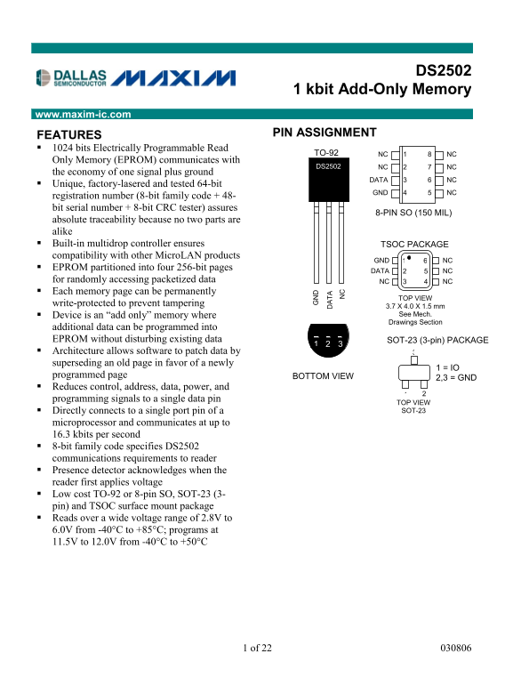
FEATURES PIN ASSIGNMENT

1024 bits Electrically Programmable Read

TO-92 NC NC

Only Memory (EPROM) communicates with

DS2502 NC NC

the economy of one signal plus ground

DATA NC

Unique, factory-lasered and tested 64-bit

GND NC

registration number (8-bit family code + 48- bit serial number + 8-bit CRC tester) assures

8-PIN SO (150 MIL)

absolute traceability because no two parts are alike Built-in multidrop controller ensures TSOC PACKAGE compatibility with other Micro LAN products

GND NC

EPROM partitioned into four 256-bit pages

DATA NC

for randomly accessing packetized data NC NC Each memory page can be permanently

TOP VIEW

write-protected to prevent tampering

3.7 X 4.0 X 1.5 mm Device is an “add only” memory where See Mech. Drawings Section

additional data can be programmed into

EPROM without disturbing existing data SOT-23 (3-pin) PACKAGE Architecture allows software to patch data by superseding an old page in favor of a newly

1 = IO

programmed page BOTTOM VIEW

2,3 = GND

Reduces control, address, data, power, and programming signals to a single data pin

TOP VIEW Directly connects to a single port pin of a SOT-23

microprocessor and communicates at up to 16.3 kbits per second 8-bit family code specifies DS2502 communications requirements to reader Presence detector acknowledges when the reader first applies voltage Low cost TO-92 or 8-pin SO, SOT-23 (3- pin) and TSOC surface mount package Reads over a wide voltage range of 2.8V to 6.0V from -40°C to +85°C; programs at 11.5V to 12.0V from -40°C to +50°C

1 of 22 030806

Page Summary Contents For MAXIM INTEGRATED PRODUCTS DS2502 1 kbit Add-Only Memory

Page 1 DS2502 1 kbit Add-Only Memory www.maxim-ic.com FEATURES PIN ASSIGNMENT 1024 bits Electrically Programmable Read TO-92 NC NC Only Memory (EPROM) communicates with DS2502 NC NC the economy of one signal...
Page 2 DS2502 ORDERING INFORMATION ORDERING INFORMATION (Ro HS) (non-Ro HS) PART PACKAGE PART PACKAGE DS2502+ TO-92 package DS2502 TO-92 package DS2502S+ 8-pin SO package DS2502S 8-pin SO package DS2502P+ 6-...
Page 3 DS2502 voltage to cause the selected EPROM bits to be programmed. The 1-Wire line must be able to provide 12 volts and 10 milliamperes to adequately program the EPROM portions of the part. Whenever pr...
Page 4 DS2502 DS2502 BLOCK DIAGRAM Figure 1 4 of 22
Page 5 DS2502 HIERARCHICAL STRUCTURE FOR 1-WIRE PROTOCOL Figure 2 64-BIT LASERED ROM Figure 3 8–Bit CRC Code 48–Bit Serial Number 8–Bit Family Code (09h) MSB LSB MSB LSB MSB LSB 1-WIRE CRC GENERATOR Figure 4...
Page 6 DS2502 1024-BITS EPROM The memory map in Figure 5 shows the 1024-bit EPROM section of the DS2502 which is configured as four pages of 32 bytes each. The 8-bit scratchpad is an additional register that...
Page 7 DS2502 or written. Writing data involves not only issuing the correct command sequence by also providing a 12- volt programming voltage at the appropriate times. To execute a write sequence, a byte of...
Page 8 DS2502 MEMORY FUNCTION FLOW CHART Figure 6 8 of 22
Page 9 DS2502 MEMORY FUNCTION FLOW CHART Figure 6 (cont’d) LEGEND: DECISION MADE BY THE MASTER DECISION MADE BYDS2502 9 of 22
Page 10 DS2502 MEMORY FUNCTION FLOW CHART Figure 6 (cont’d) 10 of 22
Page 11 DS2502 READ MEMORY [F0H] The Read Memory command is used to read data from the 1024-bit EPROM data field. The bus master follows the command byte with a 2-byte address (TA1=(T7:T0), TA2=(T15:T8)) that...
Page 12 DS2502 address and continuing until the end of a 32-byte page is reached. At that point the bus master will send eight additional read time slots and receive an 8-bit CRC that is the result of shiftin...
Page 13 DS2502 significant byte of the new two-byte address will also be loaded into the 8-bit CRC generator as a starting value. The bus master will issue the next byte of data using eight write time slots. ...
Page 14 DS2502 contains 0s in the same bit positions as the data byte, the programming was successful and the DS2502 will automatically increment its address counter to select the next byte in the EPROM Statu...
Page 15 DS2502 A multidrop bus consists of a 1-Wire bus with multiple slaves attached. At regular speed the 1-Wire bus has a maximum data rate of 16.3 kbits per second. If the bus master is also required to p...
Page 16 DS2502 DS2502 EQUIVALENT CIRCUIT Figure 7 BUS MASTER CIRCUIT Figure 8 16 of 22
Page 17 DS2502 ROM FUNCTIONS FLOW CHART Figure 9 17 of 22
Page 18 DS2502 Skip ROM [CCH] This command can save time in a single-drop bus system by allowing the bus master to access the memory functions without providing the 64-bit ROM code. If more than one slave is ...
Page 19 DS2502 CRC GENERATION The DS2502 has an 8-bit CRC stored in the most significant byte of the 64-bit ROM. The bus master can compute a CRC value from the first 56 bits of the 64-bit ROM and compare it ...
Page 20 DS2502 READ/WRITE TIMING DIAGRAM Figure 11 Write-one Time Slot DS2502 SAMPLING WINDOW 60 s  t SLOT < 120 s 1 s  t LOW1 < 15 s 1 s  t REC < Write-zero Time Slot DS2502 SAMPLING WINDOW ...
Page 21 DS2502 PROGRAM PULSE TIMING DIAGRAM Figure 12 21 of 22
Page 22 DS2502 ABSOLUTE MAXIMUM RATINGS* Voltage on any Pin Relative to Ground -0.5V to +12.0V Operating Temperature -40°C to +85°C Storage Temperature -55°C to +125°C Soldering Temperature 260°C for 10 secon...
Page 23 DS2502 NOTES: 1. All voltages are referenced to ground. 2. VPUP = external pullup voltage. 3. Input load is to ground. 4. An additional reset or communication sequence cannot begin until the reset hig...

Manual Details

Brand Maxim Integrated
Pages 23
File Size 387.01 KB
Published May 26, 2026
82 views

Enter the captcha to get the download link:

captcha

Frequently Asked Questions

How is data uniqueness guaranteed for this device?

It features a factory-lasered registration number including a unique 48-bit serial number and an 8-bit CRC.

What communication protocol does the DS2502 use?

It uses the 1-Wire protocol, requiring only a single data lead and ground return for power and data transfer.

Can I update data if some pages are read-only?

Yes; new data must be appended rather than overwriting existing data, and pages can be write-protected to prevent tampering.

What is the wide operating temperature range?

The device operates in the wide range of -40°C to +85°C for read operations.