# A B C D E F G H I J K L M N O P Q R S T U V W X Y Z

MAXIM INTEGRATED DS2780 Standalone Fuel Gauge IC User's Manual

Summary

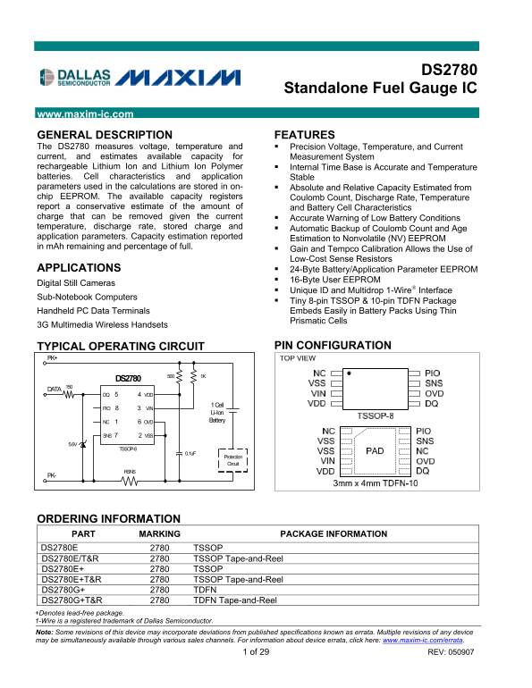
The DS2780 is a high-precision, standalone fuel gauge IC designed for monitoring rechargeable Li-Ion and Li-Polymer batteries. It accurately measures voltage, temperature, and current while providing reliable estimates of available charge capacity and State of Charge via Coulomb Count technology. Essential for battery management in portable electronics (e.g., cameras, handheld terminals), this manual provides comprehensive technical specifications, operational guidelines, pin configurations, and integration details necessary for seamless system design.
📄 Preview PAGE OF 29

Page 1 Text Content

DS2780

Standalone Fuel Gauge IC

www.maxim-ic.com

GENERAL DESCRIPTION FEATURES The DS2780 measures voltage, temperature and Precision Voltage, Temperature, and Current current, and estimates available capacity for Measurement System rechargeable Lithium Ion and Lithium Ion Polymer Internal Time Base is Accurate and Temperature batteries. Cell characteristics and application Stable parameters used in the calculations are stored in on- Absolute and Relative Capacity Estimated from chip EEPROM. The available capacity registers Coulomb Count, Discharge Rate, Temperature report a conservative estimate of the amount of and Battery Cell Characteristics charge that can be removed given the current Accurate Warning of Low Battery Conditions temperature, discharge rate, stored charge and

Automatic Backup of Coulomb Count and Age

application parameters. Capacity estimation reported

Estimation to Nonvolatile (NV) EEPROM

in m Ah remaining and percentage of full.

Gain and Tempco Calibration Allows the Use of Low-Cost Sense Resistors

APPLICATIONS 24-Byte Battery/Application Parameter EEPROM

16-Byte User EEPROM

Digital Still Cameras

Unique ID and Multidrop 1-Wire® Interface

Sub-Notebook Computers

Tiny 8-pin TSSOP & 10-pin TDFN Package Handheld PC Data Terminals Embeds Easily in Battery Packs Using Thin Prismatic Cells

3G Multimedia Wireless Handsets

TYPICAL OPERATING CIRCUIT PIN CONFIGURATION

DS2780

DQ 5 4 VDD

1 Cell

PIO 8 3 VIN

Li-Ion NC 1 6 OVD Battery

SNS 7 2 VSS

TSSOP-8

Protection Circuit

ORDERING INFORMATION PART MARKING PACKAGE INFORMATION DS2780E 2780 TSSOP DS2780E/T&R 2780 TSSOP Tape-and-Reel DS2780E+ 2780 TSSOP DS2780E+T&R 2780 TSSOP Tape-and-Reel DS2780G+ 2780 TDFN DS2780G+T&R 2780 TDFN Tape-and-Reel +Denotes lead-free package. 1-Wire is a registered trademark of Dallas Semiconductor. Note: Some revisions of this device may incorporate deviations from published specifications known as errata. Multiple revisions of any device may be simultaneously available through various sales channels. For information about device errata, click here: www.maxim-ic.com/errata. 1 of 29 REV: 050907

Page Summary Contents For MAXIM INTEGRATED DS2780 Standalone Fuel Gauge IC User's Manual

Page 1 DS2780 Standalone Fuel Gauge IC www.maxim-ic.com GENERAL DESCRIPTION FEATURES The DS2780 measures voltage, temperature and Precision Voltage, Temperature, and Current current, and estimates available ...
Page 2 DS2780 Standalone Fuel Gauge IC ABSOLUTE MAXIMUM RATINGS Voltage Range on Any Pin Relative to VSS -0.3V to +6.0V Voltage on VIN Relative to VSS -0.3V to (VDD + 0.3V) Operating Temperature Range -40°C ...
Page 3 DS2780 Standalone Fuel Gauge IC PARAMETER SYMBOL CONDITIONS MIN TYP MAX UNITS Current Gain Error IGERR (Note 2) ±1 % Full- Scale 0°C ≤ TA ≤ +70°C, Current Offset Error IOERR 2.5V ≤ VDD ≤ 4.2V - 7.82 +...
Page 4 DS2780 Standalone Fuel Gauge IC EEPROM RELIABILITY SPECIFICATION (VCC = 2.5V to 5.5V, TA = -20°C to +70°C, unless otherwise noted. Typical values are at TA = +25°C.) PARAMETER SYMBOL CONDITIONS MIN TY...
Page 5 DS2780 Standalone Fuel Gauge IC Figure 1. Block Diagram DETAILED DESCRIPTION The DS2780 operates directly from 2.5V to 5.5V and supports single cell Lithium-ion battery packs. As shown in Figure 2, th...
Page 6 DS2780 Standalone Fuel Gauge IC Figure 2. Multicell Application Example Multi-Cell Li-Ion DQ VDD (n * R) Battery SNS VSS (1) (1) Protection Circuit (1) Components improve IEC1004 Air/Contact ESD compl...
Page 7 DS2780 Standalone Fuel Gauge IC backup. When the protection circuit is connected directly to the battery the protection is absolute, no charging will occur during a protection event. With the protecti...
Page 8 DS2780 Standalone Fuel Gauge IC VIN is usually connected to the positive terminal of a single cell Lithium-Ion battery via a 1kΩ resistor. The input impedance is large enough (15MΩ) to be connected to...
Page 9 DS2780 Standalone Fuel Gauge IC The Average Current register reports an average current level over the preceding 28 seconds. The register value is updated every 28s in two’s complement form, and is th...
Page 10 DS2780 Standalone Fuel Gauge IC errors. Accumulation of charge current above the maximum register value is reported at the maximum register value (7FFFh); conversely, accumulation of discharge current...
Page 11 DS2780 Standalone Fuel Gauge IC ACR RANGE RSNS VSS - VSNS 20mΩ 15mΩ 10mΩ 5mΩ ±409.6m Vh ±20.48Ah ±27.30Ah ±40.96Ah ±81.92Ah ACCUMULATION BIAS The Accumulation Bias register (AB) allows an arbitrary bi...
Page 12 DS2780 Standalone Fuel Gauge IC Figure 11. Top Level Algorithm Diagram MODELING CELL CHARACTERISTICS In order to achieve reasonable accuracy in estimating remaining capacity, the cell performance char...
Page 13 DS2780 Standalone Fuel Gauge IC Figure 12. Cell Model Example Diagram Derivative [ppm / °C] Cell Characterization data points Active Empty Standby Empty Full: The Full curve defines how the full point...
Page 14 DS2780 Standalone Fuel Gauge IC CELL MODEL CONSTRUCTION The model is constructed with all points normalized to the fully charged state at +40°C. All values are stored in the cell parameter EEPROM bloc...
Page 15 DS2780 Standalone Fuel Gauge IC Sense Resistor Prime (RSNSP[1/Ω]): RSNSP stores the value of the sense resistor for use in computing the absolute capacity results. The resistance is stored as a 1-byte...
Page 16 DS2780 Standalone Fuel Gauge IC “learn cycle”. First, the Active Empty Point must be detected. The Learn Flag (LEARNF) is set at this point. Then, once charging starts, the charge must continue uninte...
Page 17 DS2780 Standalone Fuel Gauge IC RAAC Read Only MSB—Address 02h LSB—Address 03h 215 214 213 212 211 210 29 28 27 26 25 24 23 22 21 20 MSb LSb MSb LSb Units:1.6m Ahr Remaining Standby Absolute Capacity ...
Page 18 DS2780 Standalone Fuel Gauge IC Calculation of Results RAAC [m Ah] = (ACR[m Vh] - AE(T) * FULL40[m Vh]) * RSNSP [mhos] Note: RSNSP = 1/RSNS RSAC [m Ah] = (ACR[m Vh] - SE(T) * FULL40[m Vh]) * RSNSP [mh...
Page 19 DS2780 Standalone Fuel Gauge IC CONTROL REGISTER All CONTROL register bits are read and write accessible. The CONTROL register is recalled from Parameter EEPROM memory at power-up. Register bit values...
Page 20 DS2780 Standalone Fuel Gauge IC Figure 17. EEPROM REGISTER FORMAT Address 1Fh Bit Definition Field Bit Format Allowable Values EEC 7 Read Only EEPROM Copy Flag Set to 1 when: Copy Data command execute...
Page 21 DS2780 Standalone Fuel Gauge IC the RARC result crosses 4% boundaries. This allows the DS2780 to be located outside the protection FETs. In this manner, if a protection device is triggered, the DS2780...
Page 22 DS2780 Standalone Fuel Gauge IC Table 3. PARAMETER EEPROM MEMORY BLOCK 1 ADDRESS DESCRIPTION ADDRESS DESCRIPTION (HEX) (HEX) 60 CONTROL - Control Register 70 AE 3040 Slope 61 AB - Accumulation Bias 71...
Page 23 DS2780 Standalone Fuel Gauge IC Application Note 27, Understanding and Using Cyclic Redundancy Checks with Dallas Semiconductor Touch Memory Products. (This application note can be found on the Maxim/...
Page 24 DS2780 Standalone Fuel Gauge IC TRANSACTION SEQUENCE The protocol for accessing the DS2780 through the 1-Wire port is as follows: Initialization Net Address Command Function Command Transaction/Data T...
Page 25 DS2780 Standalone Fuel Gauge IC FUNCTION COMMANDS After successfully completing one of the net address commands, the bus master can access the features of the DS2780 with any of the function commands ...
Page 26 DS2780 Standalone Fuel Gauge IC Table 4. Function Commands BUS STATE COMMAND AFTER COMMAND DESCRIPTION PROTOCOL COMMAND BUS DATA PROTOCOL Reads data from memory starting at 69h, XX Master Rx Up to 256...
Page 27 DS2780 Standalone Fuel Gauge IC Figure 21. Net Address Command Flow Chart MASTER TX RESET PULSE DS2780 Tx PRESENCE PULSE MASTER Tx NET ADDRESS COMMAND 33h / 39h NO NO NO NO 55h F0h CCh A5h NO READ MAT...
Page 28 DS2780 Standalone Fuel Gauge IC 1-WIRE SIGNALING The 1-Wire bus requires strict signaling protocols to ensure data integrity. The four protocols used by the DS2780 are as follows: the initialization s...
Page 29 DS2780 Standalone Fuel Gauge IC Figure 23. 1-Wire Write- And Read-Time Slots WRITE 0 SLOT WRITE 1 SLOT t SLOT t SLOT t LOW0 t LOW1 t REC VPULLUP DS2780 Sample Window DS2780 Sample Window Mode MIN TYP ...

Manual Details

Brand Maxim Integrated
Pages 29
File Size 436.20 KB
Published May 26, 2026
92 views

Enter the captcha to get the download link:

captcha

Frequently Asked Questions

What types of batteries can the DS2780 measure?

It measures rechargeable Lithium Ion and Lithium-Ion Polymer batteries.

How does the DS2780 estimate remaining battery charge?

It estimates available capacity and reports a conservative estimate in mAh remaining and percentage of full.

Does the device provide temperature compensation for accuracy?

Yes, it allows Gain and Tempco Calibration to ensure accurate results.

What is the maximum operating temperature range?

The DS2780 operates reliably from -40°C to +85°C.

How are capacity estimates saved when power is lost?

Coulomb Count and Age tracking can be automatically backed up and restored to Nonvolatile (NV) EEPROM.