Page 1
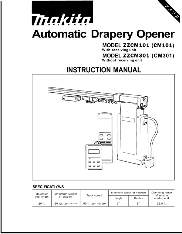
Automatic Drapery Opener MODEL ZZCMl Ol (CMl Ol) With receiving unit MODEL ZZCM301 (CM301) Without receiving unit INSTRUCTION MANUAL 1I \ a SPEC I F I CAT1 0 N S Minimum width of valance Operating ran...
Page 2
WARNING: Polarized Plugs To reduce the risk of electric shock, the motor has a polarized plug (one blade is wider than the other). This plug will f in a polarized outlet only one way. If the plug does...
Page 3
Cutting Track to Size desired overall length of the rod should be determined and the aluminum track cut according to the following equation prior to attaching the end and motor pulley housings. Length...
Page 4
Rod Assembly for Center Opening Applications Allow yourself ample working area. Depending on the model of rod assembly and the provided cable length, the end and motor pulley covers can be as far as 2...
Page 5
NOTE : When inserting the closing plates into the aluminum track, make sure the \I Pul:y \Aluminum tt .ac k cable stays on the outside of the wheels. (Fig. 4) Also check that the cable rides in the gr...
Page 6
9. Adjust center-position of draperies by I \ I I loosening the cable retaining screw on the closing plate without the overlap Cable retaining scre arm. (Fig. 8) T screw need only be loosened; be care...
Page 7
12. After again making sure the movement of the closing plates is smooth, move sleeve (6) up to the closing plate. With pliers, crimp the sleeve and cut off the excess cable. (Fig. 11 ) Fig. 1 13. The...
Page 8
Rod Assembly for One-way Operations Allow yourself ample working area. Depending on the model of rod assembly and the provided cable length, the end and motor pulley covers can be as far as 20' apart ...
Page 9
4. Loosen the cable retaining screw on the top of the remaining closing plate (with overlap arm). The screw need only be loosened; be careful not to remove it completely. (Fig. 17) Fig. 1 5. With plie...
Page 10
7. With the provided \ lrench turn the ten- sion-adjusting bolt clockwise leaving a gap between tension plates of approxi- mately 1/16", or the thickness of a nickel. (Fig. 20) NOTE : Rod lengths...
Page 11
Installation Chart Motor(s) may be attached on the right or left using the same components. rod, 1 motorsystem rods, 2 motors system Double mounting bracket
Page 12
Mounting Rod Supplied brackets will accommodate either wall or ceiling mount applications. Due to the various building materials used in construction, i.e., concrete, drywall or wood, we do not supply...
Page 13
4. Starting a the center of the rod, snap rod into brackets. (Fig. 25) Be sure to fully attach rod into bracket; a snap or click can be felt and heard when proper- ly engaged. Fig. 2! Loading Carriers...
Page 14
Attaching Motor One Motor, One Track System With rod mounted to either wall or ceiling, attach the motor to the rod. 1. Holding the motor a 45 degree angle to the track, push down on the lever on the ...
Page 15
Two Motors, Two Tracks System 1. Follow step 1 of ONE MOTOR, ONE TRACK SYSTEM starting with rod ~ , ZZCM301 (No.2) closest to window. (without receiving unit) NOTE : With the two motor system (over an...
Page 16
Remote control unit Point the remote control unit in the direction of the receiving unit. The operating range of the remote control unit is 32.8 ft. Button indicated above opens the drapery. ORAPERY R...
Page 17
24 Hour Timer - 4 Memory Functions Timer Disl )lay I TIME I Time Set Button ! ON/OFF Timer ON/OFF Button E3 Oped Close Button Memory Clear Button Memory Display Button Minute Set Button Hour Set Butto...
Page 18
Installing timer Connect the timer cord to the connecting jack marked "TIMER" on No. 1 motor (with receiving unit). Use Velcro tape provided on the back of the timer to attach the timer to t...
Page 19
Setting for open/close time *Push the F] button to change to the "Timer Set" mode. The left side open/close indicator will flicker. This indicates that the timer is now in the "Timer Se...
Page 20
Timer function r . -,\ I / To actuate the timer, push the 1 ON/OFF AM I = . -11 tzf Timer Function button. The open/close indicator will (OFF) appear. 0 To turn the timer off, push the ONIOFF , -_ but...
Page 21
OPT ION A L ACC E SSO R I ES SWITCH (For class 2 wiring only) Wall switch can only be used in conjunction with ZZCM101 (CM101). Model ZZWSIO (WSIO) Model ZZWS20 (WS20) for one motor for two motors.
Page 22
MAINTENANCE Test operat ion After assembling the complete system, connect to the power supply. Test the manual and automatic operation to be sure the system functions properly. In case of a problem, c...
Page 23
MAKITA LIMITED THREE YEAR WARRANTY Warranty Policy Every Makita motor is thoroughly inspected and tested before leaving the factory. It is warranted to be free of defects from workmanship and material...