# A B C D E F G H I J K L M N O P Q R S T U V W X Y Z

LM3914 NATIONAL SEMICONDUCTOR User's Manual

Summary

This integrated circuit is a versatile, high-precision display driver ideal for building complex analog meters and graphical indicators. It manages current regulated outputs to drive 10 LEDs in both customizable bar and dot graph modes, operating efficiently on low single supplies. The manual provides detailed specifications, application guides, and technical data required by engineers designing visual alarms or specialized metering equipment that needs reliable, programmable performance.
📄 Preview 📖 Table of Contents Contents PAGE OF 22

Page 1 Text Content

February

LM ot/B ar isplay river

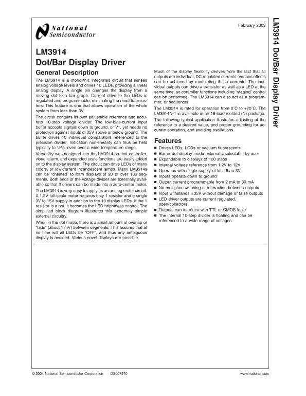
LM3914 Dot/Bar Display Driver

Much of the display flexibility derives from the fact that all

General Description

outputs are individual, DC regulated currents. Various effects

The LM3914 is monolithic integrated circuit that senses

can be achieved by modulating these currents. The indi-

analog voltage levels and drives LEDs, providing linear

vidual outputs can drive transistor as well as LED at the

analog display. single pin changes the display from

same time, so controller functions including “staging” control

moving dot to bar graph. Current drive to the LEDs is

can be performed. The LM3914 can also act as program-

regulated and programmable, eliminating the need for resis-

mer, or sequencer.

tors. This feature is one that allows operation of the whole

The LM3914 is rated for operation from 0˚C to +70˚C. The

system from less than 3V.

LM3914N-1 is available in an 18-lead molded (N) package.

The circuit contains its own adjustable reference and accu-

The following typical application illustrates adjusting of the

rate 10-step voltage divider. The low-bias-current input

reference to desired value, and proper grounding for ac-

buffer accepts signals down to ground, or V−, yet needs no

curate operation, and avoiding oscillations.

protection against inputs of 35V above or below ground. The buffer drives individual comparators referenced to the

precision divider. Indication non-linearity can thus be held Features

typically to even over wide temperature range. Drives LEDs, LCDs or vacuum fluorescents

Versatility was designed into the LM3914 so that controller, Bar or dot display mode externally selectable by user

visual alarm, and expanded scale functions are easily added Expandable to displays of steps on to the display system. The circuit can drive LEDs of many Internal voltage reference from 1.2V to 12V colors, or low-current incandescent lamps. Many LM3914s

Operates with single supply of less than 3V

can be “chained” to form displays of to over seg-

Inputs operate down to ground

ments. Both ends of the voltage divider are externally avail-

Output current programmable from m A to m A

able so that drivers can be made into zero-center meter.

No multiplex switching or interaction between outputs

The LM3914 is very easy to apply as an analog meter circuit.

Input withstands ±35V without damage or false outputs

1.2V full-scale meter requires only resistor and single

LED driver outputs are current regulated,

3V to 15V supply in addition to the display LEDs. If the

open-collectors

resistor is pot, it becomes the LED brightness control. The

Outputs can interface with TTL or CMOS logic

simplified block diagram illustrates this extremely simple

external circuitry. The internal 10-step divider is floating and can be referenced to wide range of voltages

When in the dot mode, there is small amount of overlap or “fade” (about m V) between segments. This assures that at no time will all LEDs be “OFF”, and thus any ambiguous display is avoided. Various novel displays are possible.

National Semiconductor Corporation DS007970 www.national.com

Page Summary Contents For LM3914 NATIONAL SEMICONDUCTOR User's Manual

Page 1 February LM ot/B ar isplay river LM3914 Dot/Bar Display Driver Much of the display flexibility derives from the fact that all General Description outputs are individual, DC regulated currents. Various...
Page 2 Typical Applications 0V to 5V Bar Graph Meter Note: Grounding method is typical of all uses. The 2.2µF tantalum or µF aluminum electrolytic capacitor is needed if leads to the LED supply are 6" o...
Page 3 Absolute Maximum Ratings (Note 1) Storage Temperature Range −55˚C to +150˚C If Military/Aerospace specified devices are required, Soldering Information please contact the National Semiconductor Sales ...
Page 4 Electrical Characteristics (Notes 2, 4) (Continued) Note 1: Absolute Maximum Ratings indicate limits beyond which damage to the device may occur. Operating Ratings indicate conditions for which the de...
Page 5 Typical Performance Characteristics LM Supply Current vs Operating Input Bias Temperature Current vs Temperature Reference Voltage vs Reference Adjust Pin Temperature Current vs Temperature LED Curren...
Page 6 Typical Performance Characteristics (Continued) Input Current Beyond LED Current vs Signal Range (Pin 5) Reference Loading LED Driver Current Total Divider Resistance Regulation vs Temperature Common-...
Page 7 Block Diagram (Showing Simplest Application) LM www.national.com7
Page 8 MODE PIN USE Functional Description Pin 9, the Mode Select input controls chaining of multiple The simplifed LM3914 block diagram is to give the general LM LM3914s, and controls bar or dot mode operat...
Page 9 Mode Pin Functional Description OTHER DEVICE CHARACTERISTICS LM The LM3914 is relatively low-powered itself, and since any (Continued) number of LEDs can be powered from about 3V, it is very DOT MODE ...
Page 10 Typical Applications Zero-Center Meter, 20-Segment www.national.com
Page 11 Typical Applications (Continued) LM Expanded Scale Meter, Dot or Bar *This application illustrates that the LED supply needs practically no filtering Calibration: With precision meter between pins and...
Page 12 Typical Applications (Continued) “Exclamation Point” Display LEDs light up as illustrated with the upper lit LED indicating the actual input voltage. The display appears to increase resolution and pro...
Page 13 Typical Applications (Continued) LM Bar Display with Alarm Flasher Full-scale causes the full bar display to flash. If the junction of R1 and C1 is connected to different LED cathode, the display will...
Page 14 Typical Applications (Continued) Operating with High Voltage Supply (Dot Mode Only) The LED currents are approximately 10m A, and the LM3914 outputs operate in saturation for minimum dissipation. *Thi...
Page 15 Typical Applications (Continued) LM 20-Segment Meter with Mode Switch *The exact wiring arrangement of this schematic shows the need for Mode Select (pin 9) to sense the V+ voltage exactly as it appea...
Page 16 Application Hints Non-Interacting Adjustments For Expanded Scale (Continued) Meter (4.5V to 5V, Bar or Dot Mode) APPLICATION TIPS FOR THE LM3914 ADJUSTABLE This arrangement allows independent adjustme...
Page 17 Application Hints (Continued) LM Non-Interacting Adjustments for Expanded Scale Meter (4.5V to 5V, Bar or Dot Mode) Adjusting Linearity of Several Stacked Dividers Graduations can be added to dot disp...
Page 18 Connection Diagrams Plastic Chip Carrier Package Order Number LM3914V See NS Package Number V20A Dual-in-Line Package Order Number LM3914N-1 See NS Package Number NA18A Order Number LM3914N See NS Pac...
Page 19 LM3914 MDC MWC Dot/Bar Display Driver LM Die Layout (D Step) Die/Wafer Characteristics Fabrication Attributes General Die Information Physical Die Identification Bond Pad Opening Size (min) 94µm 105µm...
Page 20 Die/Wafer Characteristics (Continued) LED NO.5 -320 LED NO.4 -526 LED NO.3 -1086 LED NO.2 -1086 IN U.S.A Tel Dial Die Fax: IN EUROPE Tel: (0) Fax: (0) IN ASIA PACIFIC Tel: (852) IN JAPAN Tel: www.nati...
Page 21 Physical Dimensions inches (millimeters) LM unless otherwise noted Note: Unless otherwise specified. 1. Standard Lead Finish: microinches /5.08 micrometer minimum lead/tin 37/63 or 15/85 on alloy or e...
Page 22 Physical Dimensions inches (millimeters) unless otherwise noted (Continued) LM ot /B ar is pl ay ri ve Dual-In-Line Package (N) Order Number LM3914N NS Package Number N18A Discontinued, Life Time Buy ...

Manual Details

Brand National
Pages 22
File Size 812.87 KB
Published June 17, 2026
1 views

Enter the captcha to get the download link:

captcha

Frequently Asked Questions

What is the operating temperature range for the LM3914?

It is rated for operation from 0˚C to +70˚C.

Can this circuit drive multiple types of displays?

Yes, it can drive LEDs, LCDs, or vacuum fluorescent lamps and supports bar or dot display modes.

How does the LM3914 handle input voltage swings?

The unit withstands ±35V without damage or false outputs, and inputs operate down to ground (0V).