LINEAR LTC3854 User's Manual
Summary
Achieve reliable power conversion with this high-efficiency, step-down DC/DC controller. Featuring an ultra small footprint (2mm × 3mm) and exceptional performance across a wide input voltage range (up to 38V), it is ideal for miniature designs. The unit offers adjustable output voltages and maximizes efficiency in demanding automotive, industrial, and communications applications. This documentation details the technical features, operational modes, optimal sensing techniques, and high-performance characteristics of the controller.
Page 1 Text Content
Step-Down DC/DC Controller in 2mm × 3mm DFN Includes FET Drivers, DCR Sensing and Accepts Inputs to 38V Mike Shriver
Wide input voltage range and reliability are desirable features in any buck converter. The LTC3854 delivers these features and more in a 2mm × 3mm DFN or MSE package. This current mode controller with integrated N-channel FET gate drivers can produce output voltages ranging from 0.8V to 5.5V over an input voltage range of 4.5V to 38V.
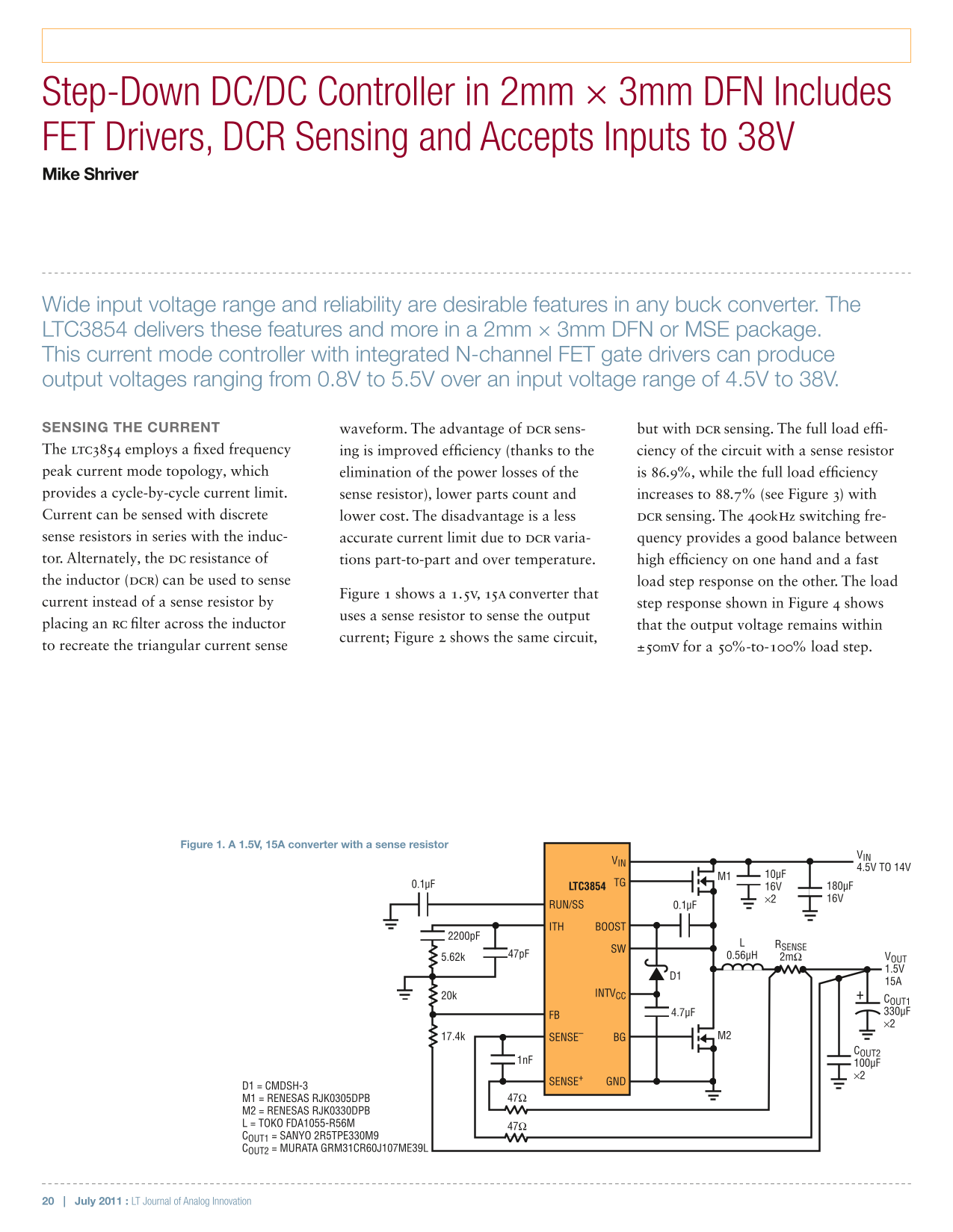
SENSING THE CURRENT waveform. The advantage of DCR sens- but with DCR sensing. The full load effi- The LTC3854 employs a fixed frequency ing is improved efficiency (thanks to the ciency of the circuit with a sense resistor peak current mode topology, which elimination of the power losses of the is 86.9%, while the full load efficiency provides a cycle-by-cycle current limit. sense resistor), lower parts count and increases to 88.7% (see Figure 3) with Current can be sensed with discrete lower cost. The disadvantage is a less DCR sensing. The 400k Hz switching fre- sense resistors in series with the induc- accurate current limit due to DCR varia- quency provides a good balance between tor. Alternately, the DC resistance of tions part-to-part and over temperature. high efficiency on one hand and a fast the inductor (DCR) can be used to sense load step response on the other. The load
Figure 1 shows a 1.5V, 15A converter that
current instead of a sense resistor by step response shown in Figure 4 shows
uses a sense resistor to sense the output
placing an RC filter across the inductor that the output voltage remains within
current; Figure 2 shows the same circuit,
to recreate the triangular current sense ±50m V for a 50%-to-100% load step.
Figure 1. A 1.5V, 15A converter with a sense resistor
4.5V TO 14V
0.1µF TG
LTC3854 16V 180µF ×2 16V
RUN/SS 0.1µF
ITH BOOST
RSENSE
47p F 0.56µH 2mΩ VOUT
20k INTVCC
COUT1 4.7µF 330µF
17.4k SENSE– BG M2
COUT2
SENSE+ GND
D1 = CMDSH-3
M1 = RENESAS RJK0305DPB 47Ω
M2 = RENESAS RJK0330DPB L = TOKO FDA1055-R56M 47Ω COUT1 = SANYO 2R5TPE330M9 COUT2 = MURATA GRM31CR60J107ME39L
20 | July 2011 : LT Journal of Analog Innovation
Page Summary Contents For LINEAR LTC3854 User's Manual
Manual Details
| Brand | Linear |
|---|---|
| Pages | 3 |
| File Size | 879.92 KB |
| Published | July 16, 2026 |
Enter the captcha to get the download link:

Frequently Asked Questions
What is the wide input voltage range supported by the LTC3854?
The controller supports a wide input voltage range, such as 4.5V to 38V or 6V to 38V.
How does DCR sensing compare to using a sense resistor for current limiting?
DCR sensing is lower cost and requires fewer parts but can be less accurate; a dedicated sense resistor offers higher accuracy at the expense of added power losses.
What general applications are suitable for this DC/DC controller?
The LTC3854 can be used in various electronics, including automotive, industrial, and communications systems.