LINEAR LT3653 User Guide and Manual
Summary
The LT3653/LT3663 are advanced monolithic buck regulators featuring programmable output current limiting technology. This manual details how these ICs solve power supply overqualification problems by accurately setting maximum operational current, eliminating the need—and massive size/cost of—components rated for extreme short-circuit conditions. Ideal for system designers developing robust battery management systems or industrial power supplies, these regulators allow precise sizing of critical components, significantly reducing application footprint and material cost without compromising reliable performance during overload events.
Page 1 Text Content
L DESIGN FEATURES
1.2A Monolithic Buck Regulator Shrinks Supply Size and Cost with Programmable Output Current Limit
by Tom Sheehan
Introduction Power supplies are often overqualified output limits the maximum power to automotive, industrial, distributed for their job. This is because power dissipation of both the supply and supply, and wall transformer applica- ICs often specify a current limit that the load, thus reducing the potential tions. is more than twice the rated output for localized heating. Monitoring and
current of the device. The power supply controlling the output current also Programmable components are sized to handle the makes for a robust solution, which is Output Current Limit
maximum current that the IC can de- able to withstand harsh overload and Monolithic switching regulators typi- liver, even if loads are unlikely to draw short circuit conditions. cally limit the peak switch current to that current during normal operation. The LT3653 and LT3663 are mono- protect the internal switch from being The components are bigger and more lithic step-down switching regulators damaged during an overload or short expensive than they need to be. that have an accurate output current circuit event. The maximum switch There is, however, an alternative: limit programmable from 400m A to peak current limit is typically more set an accurate maximum output cur- 1.2A. The LT3663 is a general pur- than two times the maximum output rent on the supply once the real world pose high voltage step-down regulator current rating of the part. While the load is known. Accurately setting the while the LT3653 is designed for use peak switch current limit prevents maximum output current reduces the with Linear Technology Bat-Track™ overstressing the IC, it does not keep required current rating of the regula- enabled battery chargers and power the entire application from overheat- tor’s power path components, thus management ICs (PMICs). The maxi- ing during an overload condition. For replacing big, expensive components mum input voltages of 30V (LT3653) example, a regulator with an output with smaller, less expensive ones. or 36V (LT3663) with 60V transient current rating of 1A is typically capable A limit on the regulator’s maximum ride through capability are well suited of providing over 2A at the output.
During an output overload condition,
BOOST L1 the power dissipation of the regula-
HIGH VOLTAGE INPUT 0.1µF
7.5V TO 30V 10V
tor could more than double, making
VIN SW
TRANSIENT C1
LT3653
TO 60V D1 thermal management more difficult.
4.7µF 50V The LT3653 and LT3663 reduce local-
ILIM ISENSE
R1 HVOKGNDVC VOUT ized hot spots by controlling the total
27.4k L2 SYSTEM 3.3µH C2 LOAD power dissipation of the application
WALL VBUS WALLVC SW 22µF
with a programmable, accurate cur-
ADAPTER C4 6.3V 10µF rent limit. 6.3V VOUT OVGATE LTC4098 Conservative design principles call
IDGATE for power path components that are
6.04k (OPTIONAL)
OVSENS
D0–D2 rated for worst-case currents. In the
TO µC BAT
TO µC CHRG
above example, where a 1A part is
NTC BATSENS
PROGCLPROG GND SINGLE-CELL capable of delivering 2A, the power
Li-Ion
path components must be sized for
0.1µF 3.01k 1k greater than 2A, because during an output short circuit or overload the inductor and diode can conduct up
L1 = TDK, VLCF5020T-4R7NIR7-1 L2 = COILCRAFT, LPS4018-332MLC to 2A. In contrast, the Power Path M1 = VISHAY, Si 2333DS
D1 = DIODES INC., DFLS240 components in LT3653 and LT3663 SEE THE LTC4098 DATASHEET FOR MORE INFORMATION applications are sized based on the
ON CONFIGURING THE NTC BATTERY TEMPERATURE
programmed maximum output cur-
QUALIFICATION OR REDUCED IDEAL DIODE IMPEDANCE.
rent limit. Therefore, an application
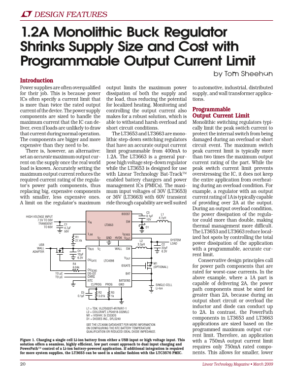
Figure 1. Charging a single cell Li-ion battery from either a USB input or high voltage input. This
with a 750m A output current limit
solution offers a seamless, highly efficient, low part count approach to dual input charging and
requires only 750m A rated compo-
Power Path™ control of a Li-ion battery-powered application. If additional integration is required for more system supplies, the LT3653 can be used in a similar fashion with the LTC3576 PMIC. nents. This allows for smaller, lower
Linear Technology Magazine • March 2009
Page Summary Contents For LINEAR LT3653 User Guide and Manual
Manual Details
| Brand | Linear |
|---|---|
| Pages | 3 |
| File Size | 234.54 KB |
| Published | June 17, 2026 |
Enter the captcha to get the download link:

Frequently Asked Questions
What is the primary benefit of using LT3653/LT3663?
They reduce localized heating and allow for smaller, less expensive power path components by controlling total power dissipation.
How do the LT3653 and LT3663 manage overloads or short circuits?
They set a programmable maximum output current limit, preventing damaging events to internal switches and allowing component sizing based on controlled ratings.
What is the ideal use case for the LT8410-1?
It is suitable for low power applications using impedance sources like coin cell batteries due to its ultralow quiescent current and soft start features.