Hitachi 2SC4877 User Guide
Summary
This document provides comprehensive technical specifications for the 2SC4877, a reliable NPN transistor designed for high-voltage applications. Featuring a built-in damper diode and an isolated TO-3PFM package, this component is ideal for circuit designers needing robust performance up to 1500V. The manual details critical electrical characteristics including saturation voltages, DC current gain (hFE), maximum power dissipation curves, and operational parameters across varying temperatures, ensuring optimal integration into your electronic device.
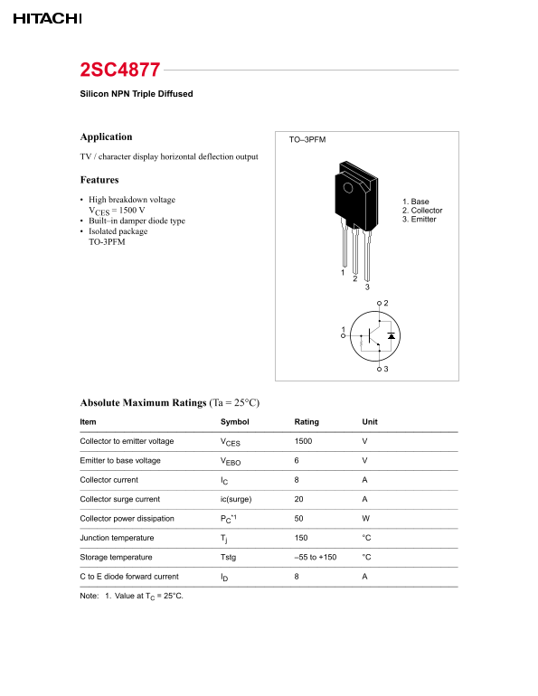
Page 1 Text Content
2SC4877 Silicon NPN Triple Diffused
Application
TO–3PFM
TV / character display horizontal deflection output
Features High breakdown voltage 1. Base VCES = 1500 V 2. Collector
Built–in damper diode type 3. Emitter
Isolated package TO-3PFM
Absolute Maximum Ratings (Ta = 25°C) Item Symbol Rating Unit ——————————————————————————————————————————— Collector to emitter voltage VCES ——————————————————————————————————————————— Emitter to base voltage VEBO ——————————————————————————————————————————— Collector current IC ——————————————————————————————————————————— Collector surge current ic(surge) ——————————————————————————————————————————— Collector power dissipation PC*1 ——————————————————————————————————————————— Junction temperature Tj °C ——————————————————————————————————————————— Storage temperature Tstg –55 to +150 °C ——————————————————————————————————————————— C to E diode forward current ID ——————————————————————————————————————————— Note: 1. Value at TC = 25°C.
Page Summary Contents For Hitachi 2SC4877 User Guide
Manual Details
| Brand | Hitachi |
|---|---|
| Pages | 4 |
| File Size | 21.74 KB |
| Published | June 03, 2026 |
Enter the captcha to get the download link:

Frequently Asked Questions
What is the maximum listed collector power dissipation?
The maximum collector power dissipation (Pc) is 50 W.
What voltage range can the device withstand in storage?
The transistor supports a storage temperature range from -55 to +150 °C.
What are the key protective features of this component?
It includes a built-in damper diode type and an isolated package TO-3PFM.
What is the maximum collector voltage rating?
The high breakdown voltage (VCES) rating for the collector is 1500 V.