Fairchild MM74C154 4-Line to 16-Line Decoder/Demultiplexer Data Sheet
Summary
This highly reliable 4-line to 16-line CMOS decoder functions as a precise demultiplexer chip, operating efficiently within a 3V to 15V range. This product is ideal for integration into complex systems requiring address decoding and signal routing. The accompanying manual provides comprehensive technical documentation, including detailed electrical characteristics, pin assignments, switching timing diagrams, and operational guidelines. It is essential reading for engineers designing advanced circuits in medical electronics, industrial automation, alarm systems, and computer applications.
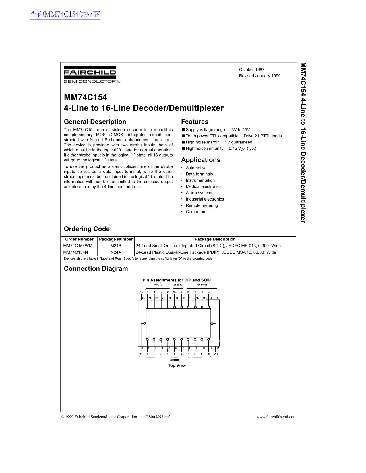
Page 1 Text Content
查询MM74C154供应商
74C 154 4-L in e to 16-L in e D eco er/D em ltip lexer
October 1987 Revised January 1999
MM74C154 4-Line to 16-Line Decoder/Demultiplexer General Description Features The MM74C154 one of sixteen decoder is a monolithic Supply voltage range: 3V to 15V complementary MOS (CMOS) integrated circuit con-
Tenth power TTL compatible: Drive 2 LPTTL loads
structed with N- and P-channel enhancement transistors.
High noise margin: 1V guaranteed
The device is provided with two strobe inputs, both of
High noise immunity: 0.45 VCC (typ.)
which must be in the logical “0” state for normal operation. If either strobe input is in the logical “1” state, all 16 outputs will go to the logical “1” state. Applications To use the product as a demultiplexer, one of the strobe
Automotive
inputs serves as a data input terminal, while the other
Data terminals
strobe input must be maintained in the logical “0” state. The
Instrumentation
information will then be transmitted to the selected output
as determined by the 4-line input address. Medical electronics Alarm systems Industrial electronics Remote metering Computers
Ordering Code: Order Number Package Number Package Description MM74C154WM M24B 24-Lead Small Outline Integrated Circuit (SOIC), JEDEC MS-013, 0.300” Wide MM74C154N N24A 24-Lead Plastic Dual-In-Line Package (PDIP), JEDEC MS-010, 0.600” Wide Devices also available in Tape and Reel. Specify by appending the suffix letter “X” to the ordering code.
Connection Diagram
Pin Assignments for DIP and SOIC
Top View
© 1999 Fairchild Semiconductor Corporation DS005893.prf www.fairchildsemi.com
Page Summary Contents For Fairchild MM74C154 4-Line to 16-Line Decoder/Demultiplexer Data Sheet
Manual Details
| Brand | Fairchild |
|---|---|
| Pages | 6 |
| File Size | 51.90 KB |
| Published | July 15, 2026 |
Enter the captcha to get the download link:

Frequently Asked Questions
What is the required supply voltage range for the MM74C154?
The device operates within a supply voltage range of 3V to 15V.
How must I configure the strobe input when using it as a demultiplexer?
The Data Terminal strobe input must be maintained in the logical “0” state for normal operation.
What happens if both strobe inputs are simultaneously in the logical “1” state?
If either strobe input is set to a logical “1” state, all 16 outputs will go to the logical “1” state.
Are there different packages or suffixes available for purchasing this device?
Yes, it is available in SOIC and PDIP packages, and you can append the suffix letter 'X' to specify Tape and Reel.