Fairchild KSR1009 Data Sheet
Summary
This datasheet from Fairchild Semiconductor documents the KSR1009 NPN epitaxial silicon transistor with a built-in bias resistor of 4.7 kilohms, housed in a TO-92 through-hole package and complemented by the KSR2009 PNP type. Intended for switching circuits, inverter, interface, and driver circuit applications, the device offers a collector-emitter breakdown voltage of 40 V, collector current of 100 mA, DC current gain from 100 to 600 at 1 mA, and a current gain-bandwidth product of 250 MHz. The
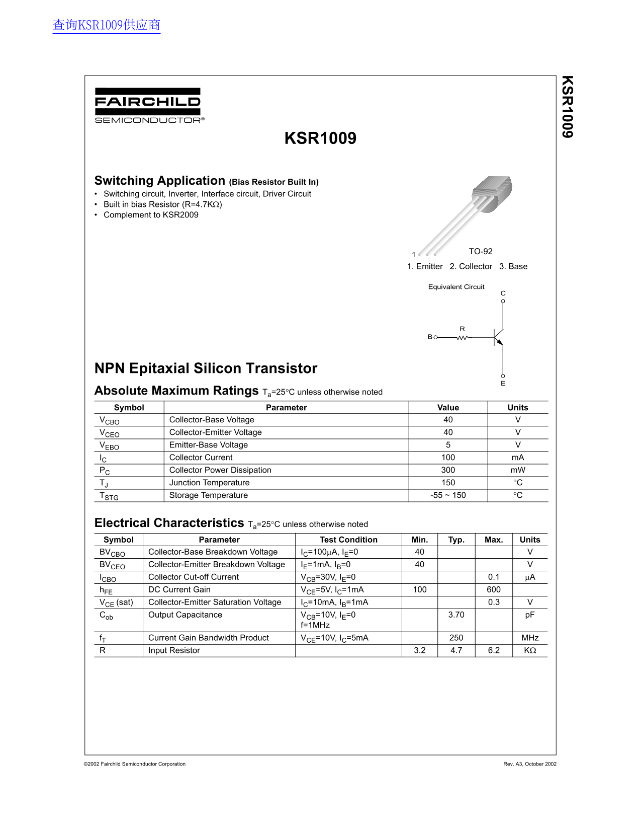
Page 1 Text Content
查询KSR1009供应商
KSR1009
Switching Application (Bias Resistor Built In) Switching circuit, Inverter, Interface circuit, Driver Circuit Built in bias Resistor (R=4.7KΩ) Complement to KSR2009
TO-921
1. Emitter 2. Collector 3. Base
Equivalent Circuit
NPN Epitaxial Silicon Transistor Absolute Maximum Ratings Ta=25°C unless otherwise noted Symbol Parameter Value Units
VCBO Collector-Base Voltage
VCEO Collector-Emitter Voltage
VEBO Emitter-Base Voltage IC Collector Current m A PC Collector Power Dissipation m W TJ Junction Temperature °C TSTG Storage Temperature -55 ~ 150 °C
Electrical Characteristics Ta=25°C unless otherwise noted Symbol Parameter Test Condition Min. Typ. Max. Units BVCBO Collector-Base Breakdown Voltage IC=100µA, IE=0
BVCEO Collector-Emitter Breakdown Voltage IE=1m A, IB=0 ICBO Collector Cut-off Current VCB=30V, IE=0 0.1 µA h FE DC Current Gain VCE=5V, IC=1m A VCE (sat) Collector-Emitter Saturation Voltage IC=10m A, IB=1m A 0.3 Cob Output Capacitance VCB=10V, IE=0 3.70 p F
f=1MHz
f T Current Gain Bandwidth Product VCE=10V, IC=5m A MHz
Input Resistor 3.2 4.7 6.2 KΩ
©2002 Fairchild Semiconductor Corporation Rev. A3, October 2002
Page Summary Contents For Fairchild KSR1009 Data Sheet
Manual Details
| Brand | Fairchild |
|---|---|
| Pages | 4 |
| File Size | 30.44 KB |
| Published | July 07, 2026 |
Enter the captcha to get the download link:

Frequently Asked Questions
What are the absolute maximum operating ratings for this transistor?
The Collector-Base Voltage (V_CBO) and Collector-Emitter Voltage (V_CEO) are both 40 V. The Emitter-Base Voltage (V_EBO) is 5 V.
How much power can the device dissipate?
The maximum rated collector power dissipation (P_C) is 300 mW. However, this rating derates with ambient temperature.
What is the recommended package type for compatibility?
This transistor comes in a TO-92 package.
Are there specific limitations for life support equipment?
No, Fairchild's products are not authorized for use as critical components in life support devices or systems without explicit written approval.