Fairchild KSR1001 Data Sheet
Summary
The KSR1001 is a high-performance NPN epitaxial Silicon Switching Transistor, ideal for interface circuits, inverter designs, and driver applications. This comprehensive datasheet provides detailed electrical specifications, including absolute maximum ratings, saturation voltages, current gain data, and typical input/output performance curves. It is essential documentation for electronics engineers and circuit designers who require reliable components for optimizing power management and switching functionality in new industrial or consumer devices.
Page 1 Text Content
查询KSR1001供应商
KSR1001
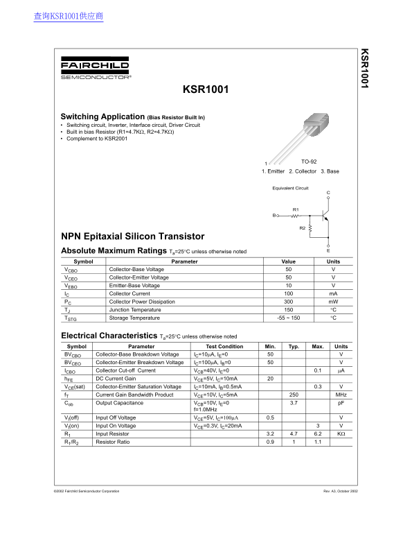
Switching Application (Bias Resistor Built In) Switching circuit, Inverter, Interface circuit, Driver Circuit Built in bias Resistor (R1=4.7KΩ, R2=4.7KΩ) Complement to KSR2001
TO-921
1. Emitter 2. Collector 3. Base
Equivalent Circuit
NPN Epitaxial Silicon Transistor Absolute Maximum Ratings Ta=25°C unless otherwise noted Symbol Parameter Value Units
VCBO Collector-Base Voltage VCEO Collector-Emitter Voltage VEBO Emitter-Base Voltage IC Collector Current m A PC Collector Power Dissipation m W TJ Junction Temperature °C
TSTG Storage Temperature -55 ~ 150 °C
Electrical Characteristics Ta=25°C unless otherwise noted Symbol Parameter Test Condition Min. Typ. Max. Units BVCBO Collector-Base Breakdown Voltage IC=10µA, IE=0
BVCEO Collector-Emitter Breakdown Voltage IC=100µA, IB=0 ICBO Collector Cut-off Current VCB=40V, IE=0 0.1 µA h FE DC Current Gain VCE=5V, IC=10m A VCE(sat) Collector-Emitter Saturation Voltage IC=10m A, IB=0.5m A 0.3 f T Current Gain Bandwidth Product VCE=10V, IC=5m A MHz Cob Output Capacitance VCB=10V, IE=0 3.7 p F
f=1.0MHz
VI(off) Input Off Voltage VCE=5V, IC=100µΑ 0.5
VI(on) Input On Voltage VCE=0.3V, IC=20m A
R1 Input Resistor 3.2 4.7 6.2 KΩ
R1/R2 Resistor Ratio 0.9 1.1
©2002 Fairchild Semiconductor Corporation Rev. A3, October 2002
Page Summary Contents For Fairchild KSR1001 Data Sheet
Manual Details
| Brand | Fairchild |
|---|---|
| Pages | 4 |
| File Size | 34.10 KB |
| Published | June 03, 2026 |
Enter the captcha to get the download link:

Frequently Asked Questions
What is the maximum safe collector current for the KSR1001?
The absolute maximum rated collector current (IC) is 100 mA.
What values do the built-in bias resistors have?
The device includes two built-in bias resistors, R1 and R2, both valued at 4.7KΩ.
Is this semiconductor suitable for life support systems?
No; Fairchild warns that these products are not authorized for use as critical components in life support devices without explicit written approval.