Dell Inspiron 15 3515 Statement of Volatility
Summary
This comprehensive technical document provides detailed product information, installation guidance, configuration procedures, and operational instructions to ensure optimal product utilization in professional environments. This document describes storage system deployment and management. It covers array configuration, RAID setup, data protection features, capacity planning, and performance optimization strategies. The manual includes detailed sections on configuration, reference, support, providing step-by-step instructions and reference information. It is designed for end users who need reliable technical documentation for deployment, management, and support of the product.
Page 1 Text Content
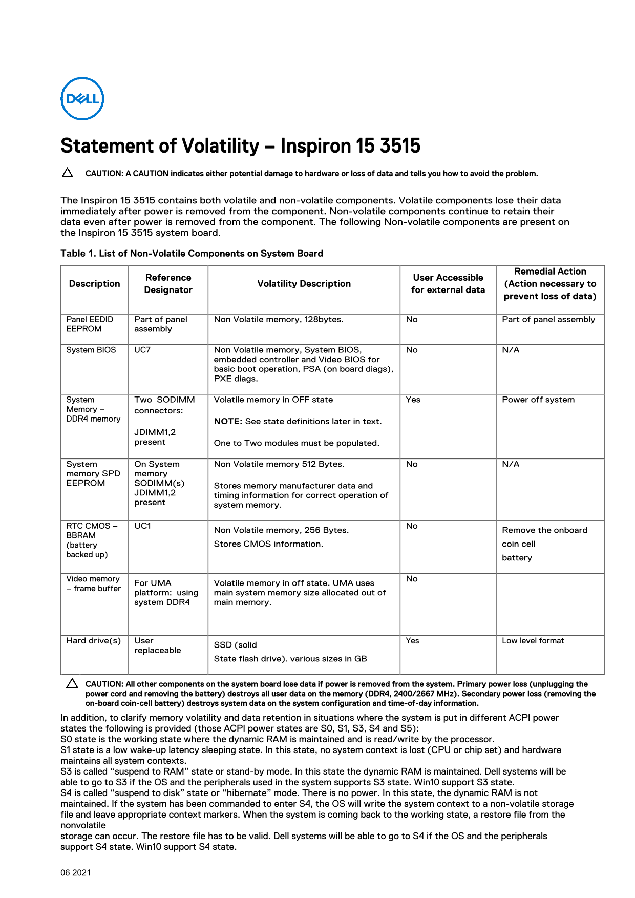
Statement of Volatility – Inspiron 15 3515 CAUTION: A CAUTION indicates either potential damage to hardware or loss of data and tells you how to avoid the problem. The Inspiron 15 3515 contains both volatile and non-volatile components. Volatile components lose their data immediately after power is removed from the component. Non-volatile components continue to retain their data even after power is removed from the component. The following Non-volatile components are present on the Inspiron 15 3515 system board. Table 1. List of Non-Volatile Components on System Board
Remedial Action
Reference User Accessible
Description Volatility Description (Action necessary to
Designator for external data
prevent loss of data)
Panel EEDID Part of panel Non Volatile memory, 128bytes. No Part of panel assembly EEPROM assembly
System BIOS UC7 Non Volatile memory, System BIOS, No N/A
embedded controller and Video BIOS for basic boot operation, PSA (on board diags), PXE diags.
System Two SODIMM Volatile memory in OFF state Yes Power off system Memory – connectors: DDR4 memory
NOTE: See state definitions later in text.
JDIMM1,2 present One to Two modules must be populated.
System On System Non Volatile memory 512 Bytes. No N/A memory SPD memory EEPROM SODIMM(s)
Stores memory manufacturer data and
JDIMM1,2
timing information for correct operation of
present
system memory.
RTC CMOS – UC1 Non Volatile memory, 256 Bytes. No Remove the onboard BBRAM
(battery Stores CMOS information. coin cell
backed up)
battery
Video memory No
For UMA Volatile memory in off state. UMA uses
– frame buffer
platform: using main system memory size allocated out of system DDR4 main memory.
Hard drive(s) User Yes Low level format
SSD (solid
replaceable
State flash drive). various sizes in GB
CAUTION: All other components on the system board lose data if power is removed from the system. Primary power loss (unplugging the power cord and removing the battery) destroys all user data on the memory (DDR4, 2400/2667 MHz). Secondary power loss (removing the on-board coin-cell battery) destroys system data on the system configuration and time-of-day information. In addition, to clarify memory volatility and data retention in situations where the system is put in different ACPI power states the following is provided (those ACPI power states are S0, S1, S3, S4 and S5): S0 state is the working state where the dynamic RAM is maintained and is read/write by the processor. S1 state is a low wake-up latency sleeping state. In this state, no system context is lost (CPU or chip set) and hardware maintains all system contexts. S3 is called “suspend to RAM” state or stand-by mode. In this state the dynamic RAM is maintained. Dell systems will be able to go to S3 if the OS and the peripherals used in the system supports S3 state. Win10 support S3 state. S4 is called “suspend to disk” state or “hibernate” mode. There is no power. In this state, the dynamic RAM is not maintained. If the system has been commanded to enter S4, the OS will write the system context to a non-volatile storage file and leave appropriate context markers. When the system is coming back to the working state, a restore file from the nonvolatile storage can occur. The restore file has to be valid. Dell systems will be able to go to S4 if the OS and the peripherals support S4 state. Win10 support S4 state.
Page Summary Contents For Dell Inspiron 15 3515 Statement of Volatility
Manual Details
| Brand | Dell |
|---|---|
| Pages | 2 |
| File Size | 145.13 KB |
| Published | June 23, 2026 |
Enter the captcha to get the download link:

Frequently Asked Questions
How do I prevent data loss when powering off the Inspiron 15 3515?
To prevent loss, ensure the system is in S3 or S4 state. If unplugging the power cord, use S4 (hibernate) to save RAM data to disk, or simply shut down properly to S5.
What components on the system board lose data if power is removed?
The primary volatile components are the DDR4 system memory and Video memory (UMA). All other components, including BIOS, SPD, and RTC CMOS, are non-volatile.
How many SODIMM slots are available for DDR4 memory?
There are two System On Memory (SOM) connectors, JDIMM1 and JDIMM2, for DDR4 memory modules.
What is the difference between S3 and S4 power states?
S3 (Suspend to RAM) maintains dynamic RAM power to save system context quickly, while S4 (Suspend to Disk) writes RAM data to non-volatile storage and cuts power to the RAM.