Danfoss Electronic Unit for BD35F Compressors (Automotive), 101N0600, 12-24V Installation Guide
Summary
This essential electronic control unit is designed for professional automotive and refrigeration applications, providing precise speed and voltage management for BD35F compressors. The comprehensive manual offers detailed installation guides, troubleshooting procedures for various operational errors, and technical specifications covering both 12V and 24V DC systems. It ensures optimal performance through advanced safety features like thermal cut-outs and fault reporting. Ideal for HVAC technicians and automotive service professionals needing reliable compressor control solutions.
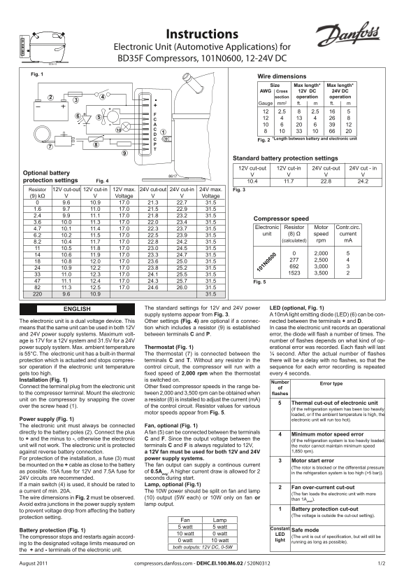
Page 1 Text Content
Instructions Electronic Unit (Automotive Applications) for
BD35F Compressors, 101N0600, 12-24V DC
Fig. 1
Wire dimensions Size Max length* Max length* AWG Cross 12V DC 24V DC section operation operation Gauge mm2 ft. m ft. m 12 2.5 16 5
12 4 13 4 26 8 10 6 20 6 39 12 8 10 33 10 66 20 *Length between battery and electronic unit Fig. 2
Standard battery protection settings 12V cut-out 12V cut-in 24V cut-out 24V cut - in
Optional battery protection settings Fig. 4 10.4 11.7 22.8 24.2
Resistor 12V cut-out 12V cut-in 12V max. 24V cut-out 24V cut-in 24V max. Fig. 3
(9) kΩ Voltage Voltage
Compressor speed
Electronic Resistor Motor Contr.circ.
unit (8) Ω speed current
(calculated) rpm m A
11.0 12.3 17.0 24.1 25.5 31.5 11.1 12.4 17.0 24.3 25.7 31.5 Fig. 5 11.3 12.5 17.0 24.6 26.0 31.5 9.6 10.9 31.5
ENGLISH The standard settings for 12V and 24V power LED (optional, Fig. 1) supply systems appear from Fig. 3. A 10m A light emitting diode (LED) (6) can be con- The electronic unit is a dual voltage device. This Other settings (Fig. 4) are optional if a connec- nected between the terminals + and D. means that the same unit can be used in both 12V tion which includes a resistor (9) is established In case the electronic unit records an operational and 24V power supply systems. Maximum volt- between terminals C and P. error, the diode will fl ash a number of times. The
age is 17V for a 12V system and 31.5V for a 24V number of fl ashes depends on what kind of op-
power supply system. Max. ambient temperature Thermostat (Fig. 1) erational error was recorded. Each fl ash will last is 55°C. The electronic unit has a built-in thermal The thermostat (7) is connected between the ¼ second. After the actual number of fl ashes protection which is actuated and stops compres- terminals C and T. Without any resistor in the there will be a delay with no fl ashes, so that the sor operation if the electronic unit temperature control circuit, the compressor will run with a sequence for each error recording is repeated gets too high. fi xed speed of 2,000 rpm when the thermostat every 4 seconds. Installation (Fig. 1) is switched on.
Number
Error type
Connect the terminal plug from the electronic unit Other fi xed compressor speeds in the range be- of to the compressor terminal. Mount the elec tro nic tween 2,000 and 3,500 rpm can be obtained when fl ashes unit on the compressor by snapping the cover a resistor (8) is installed to adjust the current (m A)
Thermal cut-out of electronic unit
over the screw head (1). of the control circuit. Resistor values for various
(If the refrigeration system has been too hea vi ly
motor speeds appear from Fig. 5.
loaded, or if the ambient temperature is high, the
Power supply (Fig. 1) electronic unit will run too hot).
The electronic unit must always be con nec ted Fan, optional (Fig. 1) directly to the battery poles (2). Con nect the plus A fan (5) can be connected between the terminals
Minimum motor speed error
to + and the minus to -, otherwise the elec tronic C and F. Since the output voltage between the
(If the refrigeration system is too heavily loaded,
unit will not work. The electronic unit is pro tec ted terminals C and F is always regulated to 12V, the motor cannot maintain minimum speed
against reverse battery connection. a 12V fan must be used for both 12V and 24V 1,850 rpm).
For protection of the installation, a fuse (3) must power supply systems.
Motor start error3
be mounted on the + cable as close to the battery The fan output can supply a continous current
(The rotor is blocked or the differential pressure
as possible. 15A fuse for 12V and 7.5A fuse for of 0.5A . A higher current draw is allowed for 2 in the refrigeration system is too high (>5 bar)). avg 24V circuits are recommended. seconds during start. If a main switch (4) is used, it should be rated to Lamp, optional (Fig.1)
Fan over-current cut-out2
a current of min. 20A. The 10W power should be split on fan and lamp
(The fan loads the electronic unit with more
The wire dimensions in Fig. 2 must be observed. (10) output (5W each) or 10W only on fan or than 1A
Avoid extra junctions in the power supply system lamp output.
Battery protection cut-out
to prevent voltage drop from affecting the battery
(The voltage is outside the cut-out setting).
protection setting.
Fan Lamp 5 watt 5 watt
Constant
Battery protection (Fig. 1) Safe mode
10 watt 0 watt LED
The compressor stops and restarts again accord- (The unit is out of specifi cation, but will still be 0 watt 10 watt light running as long as possible).
ing to the designated voltage limits measured on
both outputs: 12V DC, 0-5W
the + and - terminals of the electronic unit.
August 2011 compressors.danfoss.com - DEHC.EI.100.M6.02 / 520N0312 1/2
Page Summary Contents For Danfoss Electronic Unit for BD35F Compressors (Automotive), 101N0600, 12-24V Installation Guide
Manual Details
| Brand | Danfoss |
|---|---|
| Pages | 2 |
| File Size | 145.44 KB |
| Published | June 06, 2026 |
Enter the captcha to get the download link:

Frequently Asked Questions
What fuse ratings are needed for the power supply system?
A 15A fuse should be used for a 12V system and a 7.5A fuse for a 24V system.
How do I adjust the compressor speed?
You can obtain fixed speeds ranging from 2,000 to 3,500 rpm by installing a resistor (8) in the control circuit.
What must be done if operating at different voltages?
The electronic unit is dual voltage and can be used in both 12V and 24V power supply systems.
How does the unit signal an operational error?
The diode will flash a specific number of times; the exact count depends on what kind of power supply system is installed.