# A B C D E F G H I J K L M N O P Q R S T U V W X Y Z

Danfoss Electronic Superheat Controller - Type EKE 1D Installation Guide

Summary

This comprehensive guide provides detailed technical specifications for the EKE 1D superheat controller, essential for accurately managing cooling processes in demanding commercial environments. It is designed for HVAC engineers and facility managers overseeing heat pumps, commercial refrigeration, and industrial air conditioning systems. The manual covers electrical setup, field diagnostics, and integration details with various Danfoss valve lines (ETS, KVS, CCMT), ensuring expert installation and optimized performance of your system's thermal controls.
📄 Preview PAGE OF 15

Page 1 Text Content

ENGINEERING

Installation guide

Electronic superheat controller

Type EKE 1D English

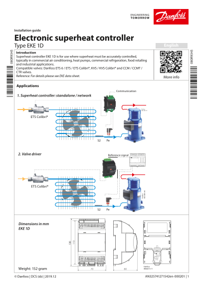
Introduction Superheat controller EKE 1D is for use where superheat must be accurately controlled, typically in commercial air conditioning, heat pumps, commercial refrigeration, food retailing and industrial applications. Compatible valves: Danfoss ETS 6 / ETS / ETS Colibri®, KVS / KVS Colibri® and CCM / CCMT / CTR valves. Reference: For details please see EKE data sheet.

More info

Applications

Communication

1. Superheat controller: standalone / network

Danfoss R64-3033.10

ETS Colibri®

S2 Pe an fo ss

2. Valve driver Reference signal

ETS Colibri®

S2 Pe

CAN RJ

Dimensions in mm EKE 1D

Danfoss Weight: 152 gram 80G8215.11

© Danfoss | DCS (sb) | 2019.12 AN325741271542en-000201 | 1

Page Summary Contents For Danfoss Electronic Superheat Controller - Type EKE 1D Installation Guide

Page 1 ENGINEERING Installation guide Electronic superheat controller Type EKE 1D English Introduction Superheat controller EKE 1D is for use where superheat must be accurately controlled, typically in comme...
Page 2 Technical specifications POWER SUPPLY EKE has galvanic isolation by switch-mode power supply. 24 V AC ± 20 %, 50/60 Hz. Maximum power consumption: 18 VA. Input voltage rating (DC): 24 V DC ± 20%, 15 W...
Page 3 General features and warnings Plastic housing features -DIN rail mounting complying with EN 50022 -Self-extinguishing V0 according to IEC 60695-11-10 and glowing/hot wire test at 960 °C according to I...
Page 4 DIN rail mounting / demounting The unit can be mounted onto a 35 mm DIN rail simply by snapping it into place and securing it with a stopper to prevent sliding. It is demounted by gently pulling the s...
Page 5 Connection overview, EKE 1D Master controller MMIGRS2 Display CANBus CAN RJ 080G0294 (optional) Supervisor EKE MMIMYK network –/ an fo ss Gateway AKS Cable connection Bu CO Ba t+ 5V I2 I2 Ba t+ I2 Pre...
Page 6 Sensor mounting: Temperature sensor –/ ~–/ 1/2 - 5/8 in. OD 12 - 16 mm an fo ss 5. an fo ss 6. 3/4 - 7/8 in. RG ND 18 - 22 mm CO 5V Ba t+ I2 I1 CO Conductive I4 B1 I3 1 - 13/8 in. B2 I2 OD paste Evapo...
Page 7 Relay Outputs EKE 1D has 1 relay output: • Type SPDT relay. Digital Output can be used to connect either a solenoid valve or an alarm. • The relays cannot be used for the direct connection of capaciti...
Page 8 Stepper Motor Output • All valves are driven in a bipolar mode with a 24 V supply chopped to control the current (Current driver). • The stepper motor is connected to the “Stepper Valve” terminals (se...
Page 9 LED indication (A) Two status LEDs to indicate operational status • Steady green = power ON • Flashing green = data transmission / initialization • Flashing red = alarm / error condition an fo ss 6B ....
Page 10 Danfoss MMIGRS2 display ACCCBI080G0075 CAN RJ Connecting external MMIGRS2 display CAN RJ MMIGRS2 display can be used to set up EKE 1D. The display can be used not only for setting up the necessary par...
Page 11 Setup wizard via MMIGRS2 display When all connections to the controller have been made, after the power is switched on, the Danfoss logo will appear for 5 seconds, then the Home screen will be display...
Page 12 Quick guide for parameter selection Apart from wizard setup, users can also use the following section which describes quick parameter settings for general applications. Driver Controller Start : Main ...
Page 13 EKE 1D – Commonly used parameter identification If the parameter value is outside the range, controller will not detect error. Parameter CAN CAN De- Description Index Subindex fault R012 Main switch 5...
Page 14 For your own notes © Danfoss | DCS (sb) | 2019.12 AN325741271542en-000201 | 14
Page 15 Related products MMIGRS2 Display Power Supply MMIMYK Gateway User interface module MMIGRS2 Display AK-PS MMIMYK device is used as a gateway Input: 100 – 240 V AC, 45 – 65 Hz to connect EKEs and the PC...