ATMEL AT90CAN64 Technical Data Handbook
Summary
The AT90CAN32/64/128 is a family of low-power, 8-bit AVR microcontroller units designed for embedded systems requiring high efficiency and robust communication. This manual provides comprehensive technical details on the integrated device features, including advanced CAN controllers, multiple serial interfaces (USART, SPI), an ADC, and flexible timing peripherals. It is essential reading for hardware engineers and system designers building reliable, optimized electronics that require low power consumption and industrial temperature range performance.
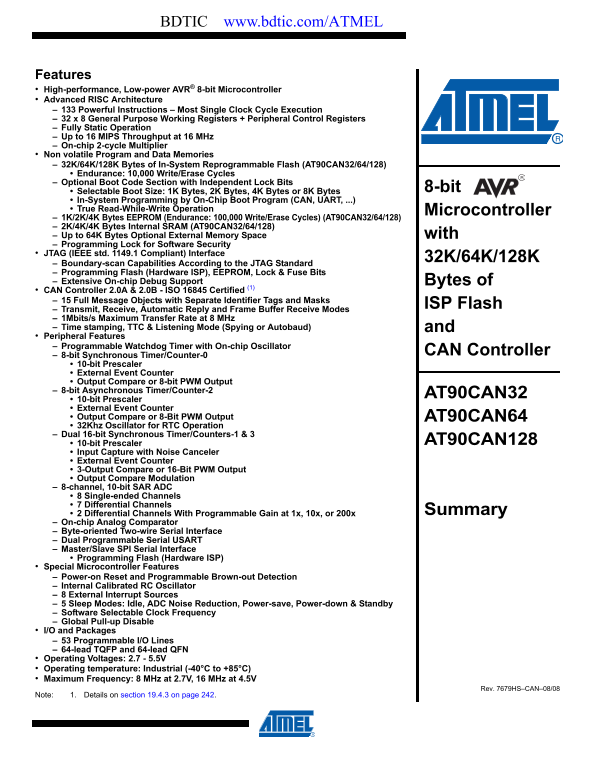
Page 1 Text Content
BDTIC www.bdtic.com/ATMEL
Features High-performance, Low-power AVR® 8-bit Microcontroller Advanced RISC Architecture 133 Powerful Instructions – Most Single Clock Cycle Execution 32 x 8 General Purpose Working Registers + Peripheral Control Registers Fully Static Operation Up to 16 MIPS Throughput at 16 MHz On-chip 2-cycle Multiplier Non volatile Program and Data Memories 32K/64K/128K Bytes of In-System Reprogrammable Flash (AT90CAN32/64/128)
Endurance: 10,000 Write/Erase Cycles Optional Boot Code Section with Independent Lock Bits
Selectable Boot Size: 1K Bytes, 2K Bytes, 4K Bytes or 8K Bytes 8-bit
In-System Programming by On-Chip Boot Program (CAN, UART, ...) True Read-While-Write Operation Microcontroller 1K/2K/4K Bytes EEPROM (Endurance: 100,000 Write/Erase Cycles) (AT90CAN32/64/128) 2K/4K/4K Bytes Internal SRAM (AT90CAN32/64/128) Up to 64K Bytes Optional External Memory Space with Programming Lock for Software Security JTAG (IEEE std. 1149.1 Compliant) Interface
Boundary-scan Capabilities According to the JTAG Standard Programming Flash (Hardware ISP), EEPROM, Lock & Fuse Bits Extensive On-chip Debug Support Bytes of CAN Controller 2.0A & 2.0B - ISO 16845 Certified (1) 15 Full Message Objects with Separate Identifier Tags and Masks
ISP Flash
Transmit, Receive, Automatic Reply and Frame Buffer Receive Modes 1Mbits/s Maximum Transfer Rate at 8 MHz Time stamping, TTC & Listening Mode (Spying or Autobaud) and Peripheral Features Programmable Watchdog Timer with On-chip Oscillator
CAN Controller
8-bit Synchronous Timer/Counter-0 10-bit Prescaler External Event Counter Output Compare or 8-bit PWM Output 8-bit Asynchronous Timer/Counter-2
AT90CAN32
10-bit Prescaler External Event Counter Output Compare or 8-Bit PWM Output AT90CAN64 32Khz Oscillator for RTC Operation Dual 16-bit Synchronous Timer/Counters-1 & 3
10-bit Prescaler AT90CAN128
Input Capture with Noise Canceler External Event Counter 3-Output Compare or 16-Bit PWM Output Output Compare Modulation 8-channel, 10-bit SAR ADC 8 Single-ended Channels 7 Differential Channels
2 Differential Channels With Programmable Gain at 1x, 10x, or 200x Summary
On-chip Analog Comparator Byte-oriented Two-wire Serial Interface Dual Programmable Serial USART Master/Slave SPI Serial Interface Programming Flash (Hardware ISP) Special Microcontroller Features Power-on Reset and Programmable Brown-out Detection Internal Calibrated RC Oscillator 8 External Interrupt Sources 5 Sleep Modes: Idle, ADC Noise Reduction, Power-save, Power-down & Standby Software Selectable Clock Frequency Global Pull-up Disable I/O and Packages 53 Programmable I/O Lines 64-lead TQFP and 64-lead QFN Operating Voltages: 2.7 - 5.5V Operating temperature: Industrial (-40°C to +85°C) Maximum Frequency: 8 MHz at 2.7V, 16 MHz at 4.5V
Rev. 7679HS–CAN–08/08
Note: 1. Details on section 19.4.3 on page 242.
Page Summary Contents For ATMEL AT90CAN64 Technical Data Handbook
Manual Details
| Brand | Atmel |
|---|---|
| Pages | 16 |
| File Size | 498.97 KB |
| Published | May 15, 2026 |
Enter the captcha to get the download link:
