ANALOG DEVICES SSM2143 –6 dB Differential Line Receiver Specification Guide User Manual
Summary
This high-performance integrated differential amplifier is designed for demanding audio applications requiring robust receiving of balanced line inputs and superior noise immunity. Key features include exceptional common-mode rejection (90 dB) and ultra-low THD, ensuring signal integrity even over long cable runs. The provided manual offers comprehensive technical specifications, functional block diagrams, and detailed performance graphs covering dynamic response, bandwidth, and various gain configurations, making it an essential resource for professional audio engineers designing reliable, low-noise equipment.
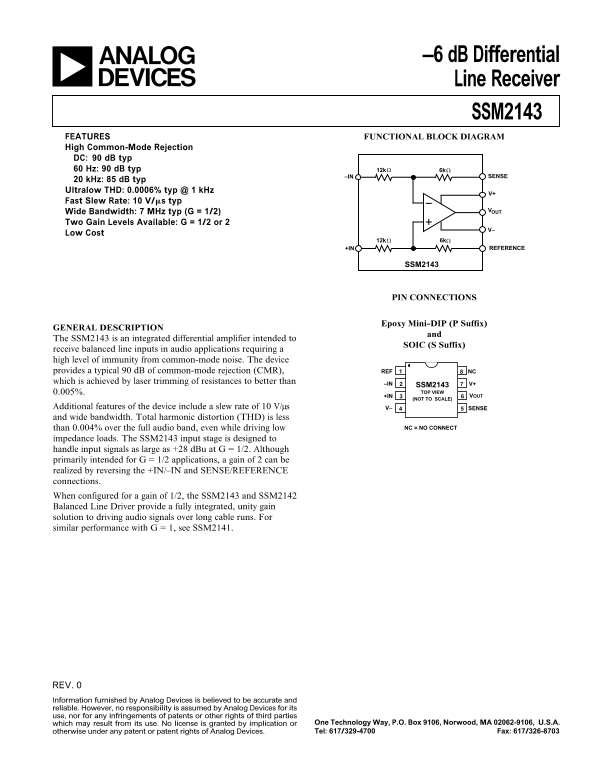
Page 1 Text Content
–6 d B Differential Line Receiver SSM2143
FEATURES FUNCTIONAL BLOCK DIAGRAM High Common-Mode Rejection DC: 90 d B typ 60 Hz: 90 d B typ 12k 6k
–IN SENSE
20 k Hz: 85 d B typ Ultralow THD: 0.0006% typ @ 1 k Hz
Fast Slew Rate: 10 V/ms typ
Wide Bandwidth: 7 MHz typ (G = 1/2) Two Gain Levels Available: G = 1/2 or 2
Low Cost
+IN REFERENCE
SSM2143
PIN CONNECTIONS
Epoxy Mini-DIP (P Suffix)
GENERAL DESCRIPTION
The SSM2143 is an integrated differential amplifier intended to
SOIC (S Suffix)
receive balanced line inputs in audio applications requiring a high level of immunity from common-mode noise. The device provides a typical 90 d B of common-mode rejection (CMR), 8REF NC which is achieved by laser trimming of resistances to better than –IN
SSM2143 V+
0.005%. TOP VIEW
+IN VOUT
(NOT TO SCALE)
Additional features of the device include a slew rate of 10 V/µs V– SENSE
OP-482
and wide bandwidth. Total harmonic distortion (THD) is less
than 0.004% over the full audio band, even while driving low NC = NO CONNECT
impedance loads. The SSM2143 input stage is designed to handle input signals as large as +28 d Bu at G = 1/2. Although primarily intended for G = 1/2 applications, a gain of 2 can be realized by reversing the +IN/–IN and SENSE/REFERENCE connections. When configured for a gain of 1/2, the SSM2143 and SSM2142 Balanced Line Driver provide a fully integrated, unity gain solution to driving audio signals over long cable runs. For similar performance with G = 1, see SSM2141.
REV. Information furnished by Analog Devices is believed to be accurate and reliable. However, no responsibility is assumed by Analog Devices for its use, nor for any infringements of patents or other rights of third parties
which may result from its use. No license is granted by implication or One Technology Way, P.O. Box 9106, Norwood, MA 02062-9106, U.S.A. otherwise under any patent or patent rights of Analog Devices. Tel: 617/329-4700 Fax: 617/326-8703
Page Summary Contents For ANALOG DEVICES SSM2143 –6 dB Differential Line Receiver Specification Guide User Manual
Manual Details
| Brand | Analog Devices |
|---|---|
| Pages | 8 |
| File Size | 364.28 KB |
| Published | May 14, 2026 |
Enter the captcha to get the download link:

Frequently Asked Questions
What is the Common-Mode Rejection (CMR)?
The SSM2143 provides a typical 90 dB of common-mode rejection, which decreases gracefully at higher frequencies.
Can this device operate with a gain other than 1/2?
Yes, while primarily for G=1/2 applications, a gain of 2 can be achieved by reversing the +IN/–IN and SENSE/REFERENCE connections. A gain of 2 is also possible using SSM2142.
What is the maximum differential input signal handling capability?
The SSM2143 input stage is designed to handle input signals up to +28 dBu at a gain of 1/2.
How is the device best used for high-fidelity audio line driving?
When configured with an associated SSM2142 and a gain of 1/2, it provides a fully integrated unity gain solution for long cable runs.