ANALOG DEVICES AD627 User Guide
Summary
The AD627 is a highly accurate, micropower instrumentation amplifier designed for robust performance in challenging environments. Featuring rail-to-rail output swing and low power consumption on both single and dual supplies, it excels in applications requiring reliable signal integrity. The manual provides comprehensive specifications covering gain settings (adjustable up to 1000), voltage offset, CMRR, and diverse operating modes. Ideal for building portable medical instruments, industrial process controls, and battery-powered data acquisition systems.
Page 1 Text Content
查询AD627供应商
Micropower, Single and Dual Supply Rail-to-Rail Instrumentation Amplifier
AD627
FEATURES FUNCTIONAL BLOCK DIAGRAM Micropower, 85 m A Max Supply Current 8-Lead Plastic DIP (N) and SOIC (R) Wide Power Supply Range (+2.2 V to 618 V) Easy to Use RG RG Gain Set with One External Resistor
–IN +VS
Gain Range 5 (No Resistor) to 1,000
+IN OUTPUT
Higher Performance than Discrete Designs
–VS REF
Rail-to-Rail Output Swing AD627
High Accuracy DC Performance 0.10% Gain Accuracy (G = 5) (AD627A) 10 ppm Gain Drift (G = 5) 125 m V Max Input Offset Voltage (AD627B) Wide supply voltage range (+2.2 V to ±18 V), and micropower 200 m V Max Input Offset Voltage (AD627A) current consumption make the AD627 a perfect fit for a wide 1 m V/8C Max Input Offset Voltage Drift (AD627B) range of applications. Single supply operation, low power con- 3 m V/8C Max Input Offset Voltage Drift (AD627A) sumption and rail-to-rail output swing make the AD627 ideal 10 n A Max Input Bias Current for battery powered applications. Its rail-to-rail output stage Noise: 38 n V/√Hz RTI Noise @ 1 k Hz (G = 100) maximizes dynamic range when operating from low supply Excellent AC Specifications voltages. Dual supply operation (±15 V) and low power con- 77 d B Min CMRR (G = 5) (AD627A) sumption make the AD627 ideal for industrial applications, 83 d B Min CMRR (G = 5) (AD627B) including 4 m A-to-20 m A loop-powered systems. 80 k Hz Bandwidth (G = 5)
The AD627 does not compromise performance, unlike other
135 ms Settling Time to 0.01% (G = 5, 5 V Step)
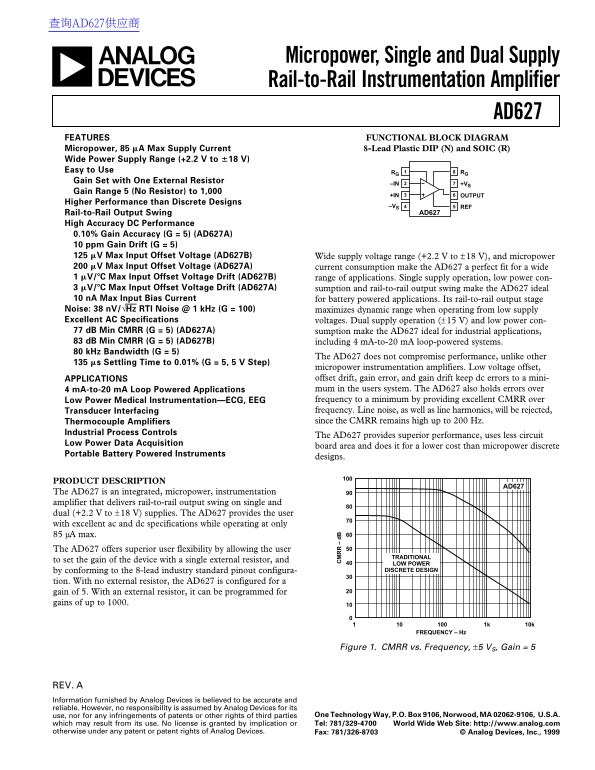
micropower instrumentation amplifiers. Low voltage offset, APPLICATIONS offset drift, gain error, and gain drift keep dc errors to a mini- 4 m A-to-20 m A Loop Powered Applications mum in the users system. The AD627 also holds errors over Low Power Medical Instrumentation—ECG, EEG frequency to a minimum by providing excellent CMRR over Transducer Interfacing frequency. Line noise, as well as line harmonics, will be rejected, Thermocouple Amplifiers since the CMRR remains high up to 200 Hz.
Industrial Process Controls
The AD627 provides superior performance, uses less circuit
Low Power Data Acquisition
board area and does it for a lower cost than micropower discrete
Portable Battery Powered Instruments
designs.
PRODUCT DESCRIPTION
AD627
The AD627 is an integrated, micropower, instrumentation amplifier that delivers rail-to-rail output swing on single and dual (+2.2 V to ±18 V) supplies. The AD627 provides the user with excellent ac and dc specifications while operating at only 85 µA max. The AD627 offers superior user flexibility by allowing the user
TRADITIONAL
to set the gain of the device with a single external resistor, and
LOW POWER by conforming to the 8-lead industry standard pinout configura- DISCRETE DESIGN
tion. With no external resistor, the AD627 is configured for a gain of 5. With an external resistor, it can be programmed for gains of up to 1000.
FREQUENCY – Hz
Figure 1. CMRR vs. Frequency, ±5 VS, Gain = 5
REV. Information furnished by Analog Devices is believed to be accurate and reliable. However, no responsibility is assumed by Analog Devices for its
use, nor for any infringements of patents or other rights of third parties One Technology Way, P.O. Box 9106, Norwood, MA 02062-9106, U.S.A. which may result from its use. No license is granted by implication or Tel: 781/329-4700 World Wide Web Site: http://www.analog.com
otherwise under any patent or patent rights of Analog Devices. Fax: 781/326-8703 © Analog Devices, Inc., 1999
Page Summary Contents For ANALOG DEVICES AD627 User Guide
Manual Details
| Brand | Analog Devices |
|---|---|
| Pages | 16 |
| File Size | 547.26 KB |
| Published | May 14, 2026 |
Enter the captcha to get the download link:

Frequently Asked Questions
What is the maximum input voltage range for single supply operation?
The input voltage range can be from +2.2 V to +36 V (or –V) – 0.1 to (+V) – 1.
How does the AD627 allow flexibility in setting its gain?
It can be programmed for gains of up to 1000 using an external resistor, or set to a default gain of 100 with no external resistor.
Is this amplifier suitable for battery-powered devices?
Yes, it features low currents (10 nA Max Input Bias Current) and operates on single supply power.
What is the minimum Common-Mode Rejection Ratio (CMRR) at 60 Hz for G=5?
The minimum CMRR at 60 Hz with V=+3V, V=0V is typically 125 dB for model AD627B.